As approved for publication by Nuclear Fusion 17/5/21: Nucl. Fusion 61 086018 (2021): https://doi.org/10.1088/1741-4326/ac09ce
Tungsten boride shields in a spherical tokamak fusion power plant
Colin G Windsor1, Jack O Astbury1, James J Davidson2, J G Morgan3 Christopher Wilson1,Samuel A Humphry-Baker2
Abstract
The favourable properties of tungsten borides for shielding the central High Temperature Superconductor (HTS) core of a spherical tokamak fusion power plant are modelled using the MCNP code. The objectives are to minimize the power deposition into the cooled HTS core, and to keep HTS radiation damage to acceptable levels by limiting the neutron and gamma fluxes. The shield materials compared are W2B, WB, W2B5 and WB4 along with a reactively sintered boride B0.329C0.074Cr0.024Fe0.274W0.299, monolithic W and WC. Five shield thicknesses between 253 and 670 mm were considered, corresponding to plasma major radii between 1400 and 2200 mm. W2B5 gave the most favourable results with a factor of ~10 or greater reduction in neutron flux and gamma energy deposition as compared to monolithic W. These results are compared with layered water-cooled shields, giving the result that the monolithic shields, with moderating boron, gave comparable neutron flux and power deposition, and (in the case of W2B5) even better performance. Good performance without water-coolant has advantages from a reactor safety perspective due to the risks associated with radio-activation of oxygen. 10B isotope concentrations between 0 and 100% are considered for the boride shields. The naturally occurring 20% fraction gave much lower energy depositions than the 0% fraction, but the improvement largely saturated beyond 40%. Thermophysical properties of the candidate materials are discussed, in particular the thermal strain. To our knowledge, the performance of W2B5 is unrivalled by other monolithic shielding materials. This is partly as its trigonal crystal structure gives it higher atomic density compared with other borides. It is also suggested that its high performance depends on it having just high enough 10 B content to maintain a constant neutron energy spectrum across the shield.
Keywords: fusion, spherical tokamaks, tungsten borides, shielding, neutrons, gamma rays
1. Introduction Spherical tokamaks present a unique opportunity to accelerate the delivery of safe, carbon-free, abundant, base-
load fusion power [1,2]. They have the plasma closer to the current-carrying central column and so make more
efficient use of the magnetic field, which decreases with distance from the column. Combining spherical
tokamaks with the high field capabilities of High Temperature Superconductors (HTS) offers a potential route to
a smaller power plant [3]. The low aspect ratio of the spherical tokamak presents a difficulty: for an HTS core of
radius Rcore necessary to provide the magnetic field, the shield thickness available for a plasma of major radius
R0, aspect ratio A and a vacuum gap g between plasma and shield is R0(A - 1)/A - Rcore - g. The lower the aspect
ratio and major radius, the thinner the space available for a shield. Several studies of candidate shielding
materials [4-9] have been made using the Monte Carlo modelling code MCNP [10]. It has been shown that the
inclusion of boron within a tungsten-based shield is advantageous, with its high neutron absorption cross section
at lower energies [5]. Various practical efforts to fabricate and test the properties of such materials have begun
[11-14] but the search is on to find the optimal boron-containing material, and optimal parameters for a tokamak
shield of specified lifetime.
The precise constraints that any shield must satisfy are not yet known. The total power deposition determines
the costs of the cryogenic plant needed to keep the HTS at operating temperatures of say 20 K. Calculations
suggest that it would be a relatively low fraction of the cost of a 200 MW fusion power plant [4]. More difficult
to calculate are the radiation damage constraints. Experimental measurements from HTS tapes irradiated in
fission reactors [15] suggest a limit of order 2x1018 cm-2 , but the energy spectrum of the flux from such reactors
is different from that behind a tokamak shield, the temperatures are several hundred K higher, and the damage
rates much faster. The present work focuses on the properties of tungsten borides as shield materials. Section 2
indicates why they have advantages. Section 3 details the MCNP methods used and the parameters calculated.
Section 4 compares the results for monolithic, homogeneous materials. Monolithic shields without cooling are
appropriate to fusion shots short enough for the shield and core to heat up adiabatically within permitted
temperature ranges. Section 5 presents practical considerations arising from the shields, including when water
cooling is introduced, the effect of varying the proportion of the favourable boron 10 isotope and some
thermophysical properties of the materials. Considerations of the activation of the materials, their decay after
shutdown, loss of 10B isotope and radiation damage, all using the FISPACT code, are the subject of further work
to be submitted shortly. Detailed computations of the heat generated within the shield and the resulting shield
temperatures are planned in further studies.
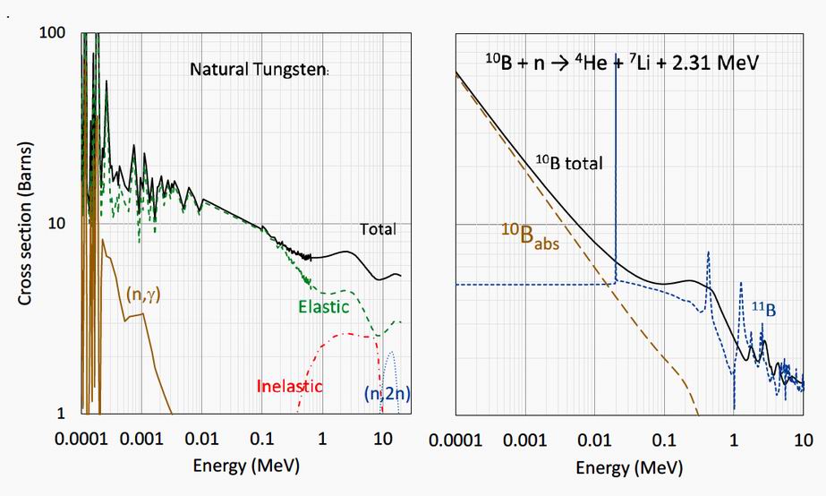
2. The advantages of tungsten and boron as shield materials The utility of tungsten and boron as shield materials arises from their favourable neutrons cross sections as
illustrated in figure 1. Tungsten has several stable isotopes: 30.64% 184W, 28.43% 186W, 26.50% 182W, 14.31%
183W and 0.12%180W. They have similar nuclear properties and figure 1 shows the neutron cross section for
natural tungsten. The tungsten cross section is dominated by elastic scattering, but between 10 and 20 MeV
there is an appreciable (n,2n) cross section. Between 1 and 8 MeV the inelastic (n,ng), cross section is
appreciable, absorbing much of the neutron energy but with the emission of gamma rays. At lower energies,
from a few eV to 1 MeV, the tungsten isotopes have many resonances for elastic and (n,g) reactions. The
occurrence of the resonance peaks at differing energies for each isotope contributes to the effectiveness of
natural tungsten as a neutron shield.
Figure 1. Boron has two stable isotopes of which the 10B isotope, with a 20% natural abundance, has the higher neutron
absorption coefficient, particularly below 10 keV, as illustrated to the right of figure 1. The 10B neutron capture
gives rise to a 4He alpha particle, a 7Li atom and a 0.478 MeV gamma ray. This transmutation means that the 10B
will be gradually depleted during operations, as will be reported in a later paper. The sub-MeV gamma ray
produced has the potentially deleterious consequences of contributing to the power deposition in the HTS core,
causing radiation damage to the shield and core, and generally adding to the radiation dose levels produced by
the tokamak during operations. There will also be changes in the thermal, mechanical, and corrosion
performance in the shield resulting from the transmutation. Isotopically concentrated 10B is widely used in the
nuclear fission industry for neutron-absorbing control rods. For this reason, this study compares the shield
performance of natural 20% abundance with shields made from 0, 40, 60, 80 and 100% isotopically enhanced
fractions of 10B.
The properties of tungsten and boron detailed above provide the key to their use in a fusion reactor neutron
shield, which must reduce the transmitted power to acceptable levels and limit radiation damage. The plasma-
facing side of the shield faces a flux of energetic 14.1 MeV neutrons from the deuterium-tritium reaction
2D + 3T = 4 He + n +17.6 MeV. The 3.5 MeV 4He particles are not a problem as their charge keeps most of them
within the plasma. The shield can reduce the power transmitted by several methods, which are illustrated in
figure S1 in the supplementary material.
(i) Elastic scattering allows many neutrons to be simply reflected back into the fusion chamber.
Tungsten atoms make a good reflector because of their high mass compared to a neutron ensures
little recoil energy and ~3 barns of elastic cross section per atom at 14 MeV. The fluxes reported
in this paper include neutrons propagating in all directions. Studies including the directional nature
of the fluxes differentiating inward and outward fluxes are in progress.
(ii) When incident neutrons collide with lighter atoms, like boron, the collisions exchange, or
moderate, the neutron energy so reducing the transmitted power. The best moderator is hydrogen
since its mass is almost the same as the neutron and the maximum energy is lost on collision. It is
for this reason that water is often used within a shield, where it can also provide cooling, although
its oxygen activation may give a problem. Boron or carbon with masses around 10 to 12 provide
intermediate moderation.
(iii) Inelastic (n,2n) reactions produce a different isotope of the same element. A typical reaction
would be 183 W + n = 182 W + 2n + γ, which is highly beneficial transforming each high energy
neutron into two lower-energy neutrons of a few MeV which are easier to shield.
(iv) Inelastic (n,nγ) neutron scattering means that the incident neutron forms a new compound nucleus
which quickly decays to release the neutron with an appreciably lower energy and with the
emission of the excess energy in the form of a gamma ray. The neutron energy is reduced by
around 1 to 7 MeV, but this energy is released as a gamma ray of comparable energy. The
transmitted neutron energy is therefore appreciably reduced but there will be a new gamma flux
leading to its own transmitted energy and needing extra gamma shielding.
(v) (n,γ) capture is common at lower neutron energies. The neutron is absorbed to form a tungsten
isotope with one higher atomic weight with the emission of a gamma ray of significant energy,
(vi) The lower energy neutrons produced by moderation or inelastic scattering become increasingly
likely to be absorbed by isotopes such as 10B with a high neutron absorption cross section which
normally increases with decreasing energy as 1/v where v is the neutron velocity, as illustrated in
figure 1. The neutron transmitted power is reduced but the absorption produces a gamma ray
leading to increased transmitted gamma power.
Gamma rays are shielded by scattering from electrons in the shield atoms, and thus need high atomic number
(number of electrons per atom) and high density (atoms/m3). Tungsten is therefore a comparatively good
element for a gamma shield, while boron is not.
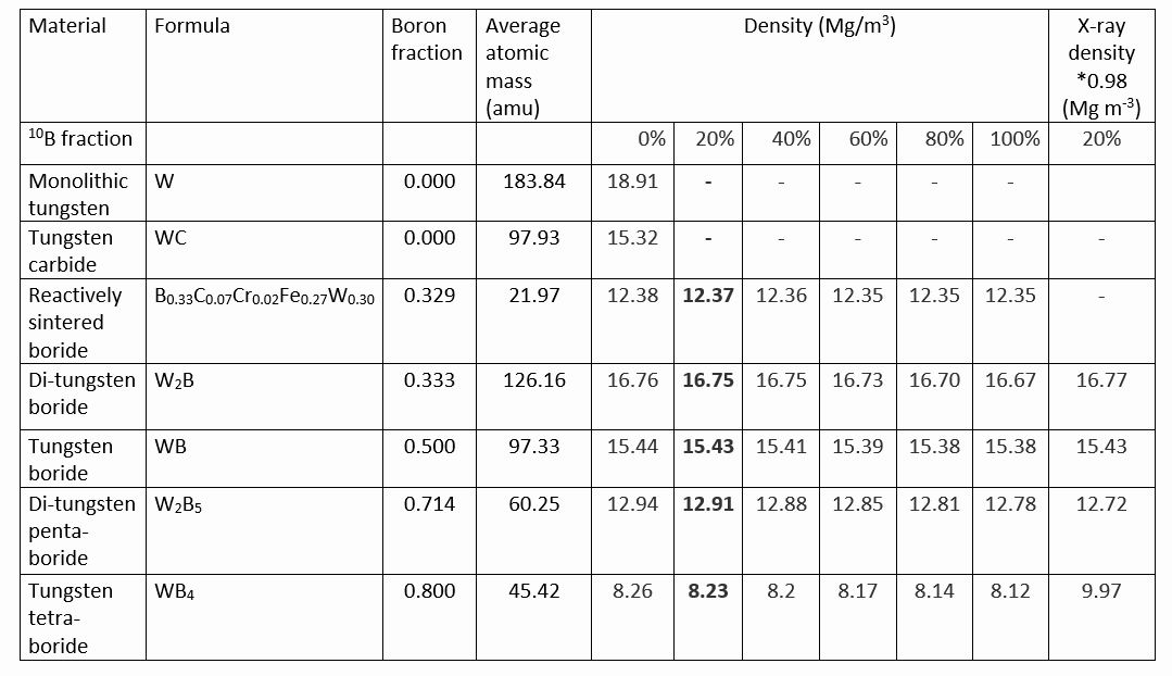
Table 1 shows the shielding materials selected for this study. Monolithic tungsten and tungsten carbide are
well known shield materials and are included for comparison. Also included is a reactively sintered iron-
tungsten borocarbide B0.329C0.074Cr0.024Fe0.274W0.299 [8], hereafter referred to as the borocarbide. The other
materials have been ordered according to their boron atomic fraction. The assumed densities for natural boron-
containing materials (20% 10B isotopic ratio), shown in heavy type, were taken from the literature [11]. The values in the table for other isotopic concentrations have been calculated from the 20% values. To correspond
to the densities used in this paper they have been multiplied by 0.98 to allow for extra porosity during bulk
manufacture. Since this and other work shows that the shield performance is very sensitive to material densities,
the densities of tungsten borides were compared with X-ray powder diffraction measurements found in [17]
using samples with the natural 20% 10B isotopic ratio. It is seen that the assumed densities agree with the X-ray calculated values to within three significant decimals except for WB4 where the assumed value is only 82.5% of the X-ray value. It has been shown that this difference is not sufficient to make any material change to the conclusions of this paper.
In most previous studies the shield design has included annular water cooling channels [4-6]. Water cooling
presents an operational challenge because of the neutron activation reaction 16O(n,p)16N; this nitrogen isotope
decays with a half-life of 7.13 s emitting a 6.129 MeV gamma ray. Besides providing cooling, the hydrogen in
the water is also an excellent neutron moderator, and this may be a key feature of its success as a shield material.
This study attempts to address this point by directly comparing monolithic shields with water-moderated
versions containing 5 radial layers of water distributed over 25 radial layers of shield.
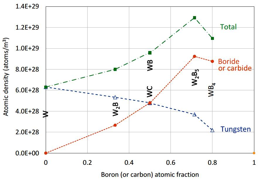
Table 1 The attenuating effectiveness of a shield depends on its constituent atomic densities. Here the tungsten density
is key to gamma attenuation, the boride (or carbide) to neutron moderation, and the boride to neutron
absorption. Figure 2 shows these atomic densities for tungsten and for boron or carbon, along with their sum
plotted against boron (or carbon) density. W2B5 is seen to lie above the trend line in all cases and to give the highest total atomic density.
Figure 2. To reduce core power deposition and shield and core irradiation, the main option available is to increase the
shield thickness, and consequently the tokamak major radius. In this study some 5 plasma major radii have been
chosen, spaced from 1400 to 2200 mm. The superconducting core has been kept constant at 250.9 mm radius.
This is consistent with the plasma properties, however in practice it is likely that engineering considerations
such as the hoop stress at the top and bottom of the toroidal field coils will determine a modest increase in core
size. The shield thickness is adjusted to keep the plasma gap between the inner plasma boundary and the first
wall constant. This gave 5 shield thicknesses between 253 and 670 mm.
To summarize the shield materials options of this study, some 7 materials, the 5 boron containing materials
each with 6 isotopic concentrations, both with and without water cooling, and with 5 major radii, are considered
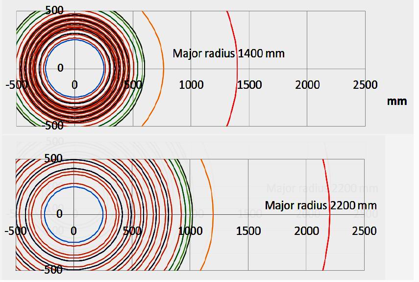
giving (5x6+2)x5x2=320 shield models. Figure 3 illustrates the radial build of the largest and smallest models.
Figure 3.
The radial build of the smallest and largest tokamak major radii considered. The central core outer radius (blue) is
fixed in size as are the thicknesses of the vacuum vessel (light green), the gap between the first wall and the plasma
boundary (dark green) and the tungsten first wall (yellow). Dark red shows the shield outer radii, and the dark blue those of the water layers. The plasma central position is shown in bright red.
3. Radiation transport modelling Neutron and photon transport calculations were performed using the code MCNP 6.2.0 [10] invoking the
FENDL 3.0 (neutron), MCPLIB84 (photon), and ENDF7U (photo-neutron) cross-section libraries. Calculations
were performed in a series of steps:
Firstly, weight windows were generated iteratively for each of the models using the automated weight
window generator (WWG) in MCNP using a tally optimized for reducing the variance of low and epithermal
energy neutrons and secondary gamma photons in the centre of the core.
Secondly, heat deposition tallies (type F6) were scored within the HTS core for both neutrons and photons
using the weight windows generated in the first stage calculation.
Thirdly, neutron-only transport models were run (in MODE N) with energy-resolved neutron flux tallies (type
F4) using the CCFE-709 energy group scheme and the variance reduction from stage one turned on; the flux
tallies were recorded within the HTS core and as a function of shielding depth. In this case, the contribution of
photo-neutrons to the neutron flux tallies were assessed for certain cases and deemed insignificant.
The energy depositions and fluxes were computed for a nominal 200 MW fusion power plant. The fusion
neutron creation matrix as a function of radius and height was provided for the 1400 mm major radius case from
the Tokamak Energy System Code as a matrix of 68 radial segments and 200 vertical segments. Finally, the
neutron flux files were input to the activation and transmutation code FISPACT, where dpa, gas rate and
10B(n,?)7Li depletion were tracked over a continuous 30-year irradiation period. The results of the FISPACT
analysis will be presented in a future publication.
Most of the results presented will correspond to tallies covering the integral over all energies of the full
distributions. In particular they are calculated for the following tallies:
1. HTS peak neutron fluence at the vertical mid-plane section within +/- 200 mm of the vertical shield
centre in cm-2 MWh-1units and its error
2. HTS mean neutron fluence in cm-2 MWh-1 units and its error
3. Total power in HTS in kW and its error
4-29. Neutron fluence for the 26 surface layers of the shield ( cm-2 MWh-1) and error
30. Neutron power in the HTS in kW with error
31. Photon power deposition in the HTS in kW with error.
The table of these 31 parameters for all the 320 calculations is given in the supplementary data. Computations
for the single case of natural W2B5 at major radius 2200 mm were performed with much improved statistics.
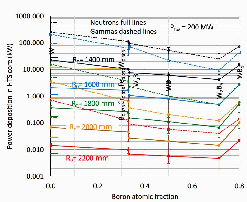
4. Comparison of monolithic boride material shields The neutron and gamma power deposition into shields of the monolithic materials with natural boron isotopic
concentration, integrated over particle energy, are shown for the monolithic materials at major radii R0 =1400 to
2200 mm in figure 4. It is seen that the gamma power deposition exceeds the neutron deposition by around an
order of magnitude. This is despite the fact that the radiation incident on the first wall comprises mainly 14.1
MeV fusion neutrons with only around 15% proportion of gammas as shown in figure 4 of reference [6].
Reference [6] showed that the mean neutron energy dropped steadily through a typical moderated neutron shield
but that the gamma power remained high, leading to the high gamma power deposition. The graphs in figure 4
show that the power deposition for both neutrons and gammas generally decreases with boron content up to
W2B5, where it forms a local trough for all the major radii considered. The relative change in power deposition
decreases with increasing device size. For example, at R0 =1400 mm W2B5 shows lower neutron power than W
by a factor of 6 or so, while at R0 =2200 mm this factor falls to ~3. It may be concluded that boron, through its
combination of neutron moderating and absorption effectiveness, make it the key element in reducing the power
deposition in these materials.
The borocarbide B0.329C0.074Cr0.024Fe0.274W0.299 has good performance at all major radii but is slightly worse
than the trend of the binary materials. This is probably because of the fraction of chromium and iron which have
less favourable gamma shielding effectiveness than tungsten.
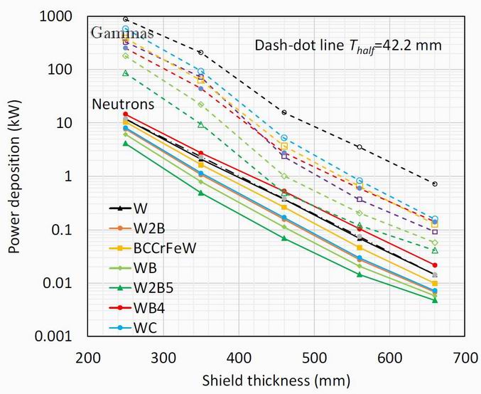
Figure 4. A different presentation of the same data is obtained by plotting the power deposition on a log scale against the
major radius for each material as shown in figure 5. The neutron power depositions are shown to follow a
roughly exponential decrease with shield thickness, corresponding to a half-power distance of 42.2 mm, as
shown by the dot-dashed line, fitted to the monolithic tungsten data. Other materials including W2B5 show a
slight upwards curvature suggesting a decreasing performance over W at larger shield thicknesses. The dashed
gamma power deposition follows a similar overall decline with shield thickness with the half-power thickness
for gammas essentially the same as that for neutrons, although there is a gradient change around 400 mm
thickness.
Figure 5.
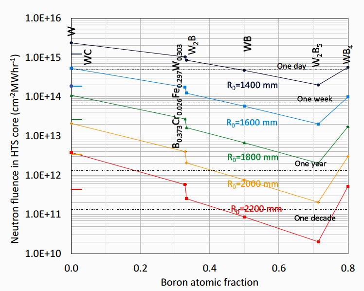
Figure 6. Another important result is the neutron flux within the HTS core. In this paper the neutron core flux quoted
will be that at the vertical mid-plane height in the tokamak where the flux is largest, although the mean flux over
the whole of the core was also calculated and is given in the supplementary data. This peak flux is important in
determining the lifetime of the HTS core material through its radiation damage. Figure 6 shows the neutron
fluence within the HTS core for all major radii again as a function of boron concentration. Also included are
estimations for the maximum possible lifetime for a given HTS material, based on HTS performance
degradation after neutron fluences of 2x 1018 cm-2 [15] at 200 MW fusion power. For example, to enable a
decade lifetime, the R0 must be at least 1800 mm, where W2B5 is the only viable candidate shield material.
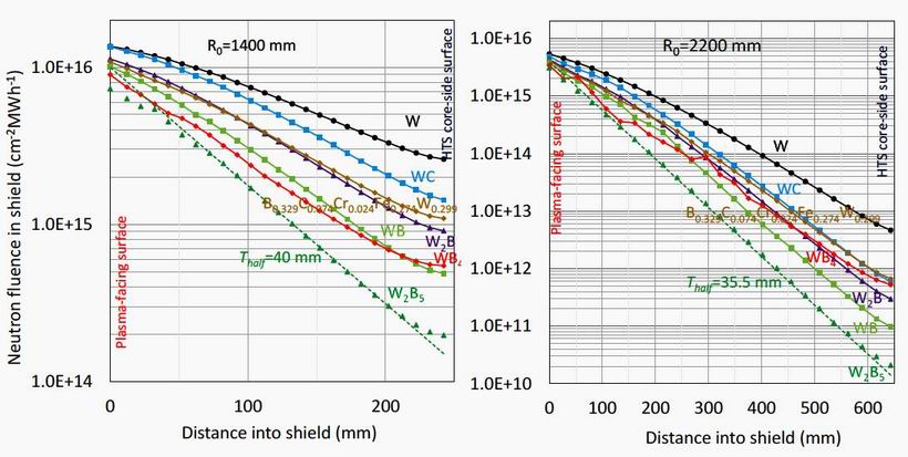
The increases in fluence over the 25 tally radii within the shield from the core-side to the plasma-facing side
are shown in figure 7 for the major radii of 1400 mm and 2200 mm. The fluence is plotted logarithmically for
each monolithic shield material as labelled. It is seen that the 643 mm thick shield at 2200 mm major radius
covers some 5 orders of magnitude compared to less than two for the 253 mm thick shield at 1400 mm radius. In
both cases W2B5 performs significantly better than the other materials. The order of performance with material
is slightly changed for the smaller major radius, with the WB and W24 at
the larger device size. Near the plasma-facing edge all the materials face a similar incident fluence and the
differences between materials are relatively low.
.
Figure 7. All the plots in figure 7 show a similar shape with a gradient build up from the plasma-facing side to a close
to exponential decrease in the centre of the shield, A similar but lesser decrease in gradient occurs close to the
HTS core side of the shield. This behaviour is illustrated by the dashed lines in figure 7 that show an exponential
decrease in fluence with the half attenuation distances shown. The deviations from the dashed lines are clearly
seen for R0 =1400 mm, although for R0 =2200 mm they are quite small. It is probable that these deviations are
partly caused by the lack of absorbing boron in the central superconducting core, and at the stainless steel and
tungsten plasma-facing components as illustrated in figure 3. Although the scales of the plots at the two radii are
very different, the half attenuation distances of the dashed lines differs only slightly.
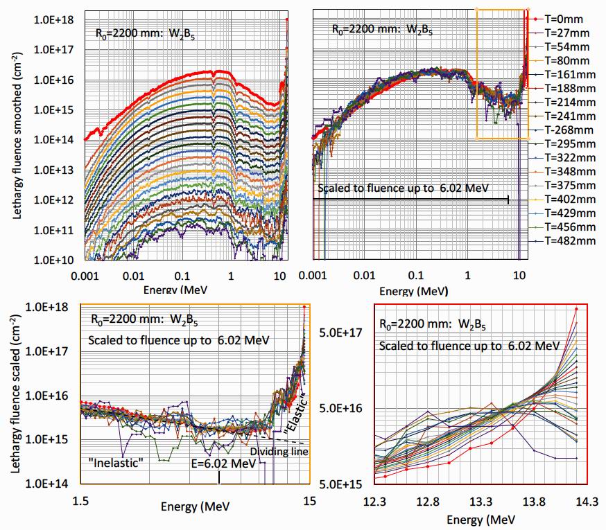
For the case of a shield of monolithic W2B5 at 2200 mm major radius results of higher accuracy were
available. The top left-hand of figure 8 shows the neutron energy lethargy spectrum as a function of distance
into the shield for this case. Lethargy spectra are appropriate when covering the large energy range from 1 keV
to over 10 MeV. In a lethargy spectrum the quantity plotted per energy bin is multiplied by the bin mean energy
and divided by the bin width in energy, so that the quantity plotted is dimensionless in energy and sums to the
total quantity. The spectra have been smoothed by averaging of 3 to 5 energy bins for the energies below 0.02
MeV and for distances into the shield above 500 mm.
A striking characteristic of the top left-hand side of figure 8 is that, with the exception of the red plasma-
facing spectrum, the shapes of the energy spectra up to around 6 MeV are remarkably constant. This feature is
revealed in the top right-hand side of figure 8, where the intensity has been scaled by the integral of the lethargy
fluence up to 6.02 MeV. There is a remarkable superposition of the fluence energy spectra from the majority of
the layers within the shield at energies below 6.02 MeV. The surprising conclusion is that the neutron energy
spectra below 6 MeV are independent of the depth into the shield!
While this superposition of the spectra occurs up to 6 MeV, at higher energies the situation is quite different.
The detail of the scaled lethargy fluence at energies above 6 MeV is revealed in the lower half of the figure
which shows the same scaled fluence between energies of 1.5 and 15 MeV (bottom left) and between 12.3 and
14.1 MeV (bottom right). The data in this region can be approximated by the exponential decay given by the
dashed line described by log10 [F(E)/F(6.02)]= - 1.9log10 [E/6.02] where F(E) is the fluence at energy E MeV.
The strong superposition of scaled fluences below 6.02 MeV, and lack of superposition above this energy
suggests quite distinct origins for the flux distributions above and below the black dashed "dividing line" shown
in the lower left figure. It is suggested that the fluence below this dividing line is caused by "inelastic" scattering
processes such as the (n,2n) and (n,nγ ) cross sections described in section 2 which reduce neutrons of energy
around 14 MeV to a broad inelastic spectrum of neutron energies centred around 0.2 MeV and remarkably
constant at all distances into the shield. In contrast the bottom right plot in figure 8 shows that there is little
superposition above 6.02 MeV and above the dividing line. This "elastic" fluence is composed of the original
14.2 MeV fusion neutrons which may have lost energy principally by elastic scattering from the tungsten and
boron atoms as they pass through the shield as detailed in section 2. With each increment into the shield, the
14.1 MeV scaled fluence decreases. At distances into the shield above 300 mm, a peak in the scaled fluence
appears below 14.1 MeV and shifts to ever lower energies.
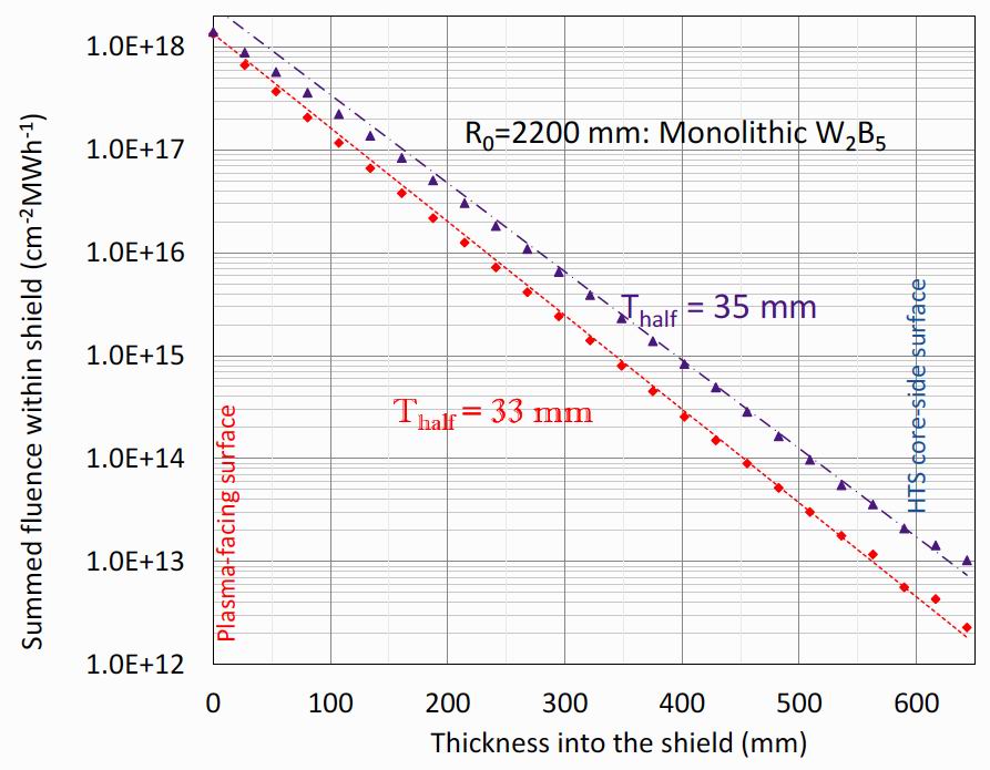
Figure 8. Making this assumption, it is straightforward to sum the elastic and inelastic components of the original
unscaled fluence at each distance into the shield as shown in figure 9. It is seen that both components start with
a similar fluence, and both decay approximately exponentially with distance into the shield as shown by the
dashed lines, with the corresponding half-distance lengths shown. The elastic component is closest to
exponential with a half-attenuation distance of 33 mm. The inelastic component has lesser decay rates near both
plasma-facing and core-facing sides as was noted for the total fluences through the shield in figure 7 again
reflecting the relative lack of absorbing boron material at these points. The result is that the ratio of the elastic to
the inelastic fluence decreases with distance into the shield from about 1 at the plasma-facing side to 5 at the
core-facing side. The elastic component has a slowly decreasing mean energy from 14.0 MeV at the plasma-
facing side to 12.8 MeV at the HTS-facing side. The inelastic component mean energy slowly decreases from
0.8 MeV at the plasma-facing side to 0.7 MeV at the HTS-facing side.
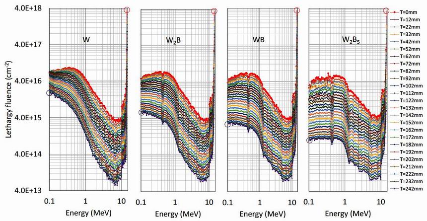
Figure 9. The scaled superposition method worked well for W2B5 at other radii, and for WB4, but not for other shield
materials. Figure 10 shows the unscaled neutron fluence energy spectra for tungsten and tungsten boride
materials with increasing boron content. The loss of superposition is seen by changes in the energy spectrum
profile and decreases inversely as the boron concentration. Superposition works well in the range 1 to 6 MeV
just to the left of the minima in the spectra, but then fails increasing badly as the energy decreases. There are
much greater fluences at the core-side of the shield than would have been expected from superposition, as
indicated by the violet circles in the figure.
Figure 10. The similarly-shaped neutron lethargy spectra through the shield observed for the boron concentration of W2B5
suggests a rationale for its exceptional performance. As the depth into the shield increases, an ever-decreasing
quantity of the broad 'inelastic' neutron spectrum will be added in proportion to the remaining 'elastic' fluence of
around 14 MeV fusion neutrons. At the same time the spectrum will be softened to lower energies by
moderation. For the total spectrum profile to be maintained, the 10B isotope absorption must be sufficient to remove the lower energy neutrons so produced. In contrast, with for example a W2B shield, the 10B absorption
is insufficient for this, and the neutron spectrum at lower energies builds up continuously with distance into the
shield as suggested by figure 10 leading to an overall larger power deposition.
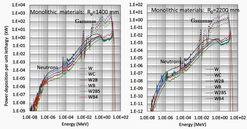
The energy spectra per unit lethargy of the deposited power into the superconducting core for the monolithic
materials are shown in figure 11 for major radii of 1400 mm (left) and 2200 mm (right). It is striking that the
gamma fluence is ~100 higher than the neutron fluence above 0.1 MeV but drops rapidly below 50 keV as its
attenuation rapidly increases. Most of the power deposition into the core is within the 0.1 to 10 MeV range for
both gammas and neutrons. The order of materials is maintained over most of the energy range, for both radii,
and for both neutrons and gammas. Comparison between the attenuations at the two major radii show a factor of
~100 for gammas above 1 MeV, but a larger ~1000 factor for neutrons which is roughly maintained over the
whole energy range. An exception is the energy range 1-14 MeV where WB4 has the highest power deposition.
The atomic fraction of boron could be critical in this energy range where figure 1 shows the boron cross section
to be low.
Figure 11.
Power energy spectra per unit lethargy of the neutron and gamma power deposition into the superconducting
core for monolithic material shields for the cases of R0 =1400 mm (left) and R0 =2200 mm (right). Full lines are neutrons, dashed are gammas. Note the very different scales for the two major radii.
5. Practical considerations of proposed shielding materials An important practical consideration in any fusion power plant is how to cool the shield. A possible solution is
to use layers of water for both cooling and moderation. For each of the chosen shield materials, and for each
boron concentration, the effects of introducing a water moderator were evaluated. The thickness of the water
layers varied from 10 mm at R0 =1400 mm to 17 mm at R0 =2200 mm. Pure water has been previously chosen as
a moderator [4-6] but because of its activation problem it may be desirable to avoid it, for example by using
channels of gaseous helium. A fixed geometry for the water layers has been used with 5 radii spaced through the
shield as was indicated in figure 3.
Figure 12 shows the neutron and gamma power depositions into the HTS core, with and without water layers
within the shield materials for major radii of 1400 mm (left) and 2200 mm (right). The presence of water layers
tends to flatten out the variation of deposited power with boron fraction with decreases at high depositions and
increases at low depositions. For tungsten and WC, the reduction is considerable. W2B5 maintains its optimal
position with the lowest deposited power at all major radii, and with this material, there is always a detrimental
effect from the addition of water layers. In the larger radius device, the detrimental effect of water extends to all
of the pure tungsten boride materials.
.
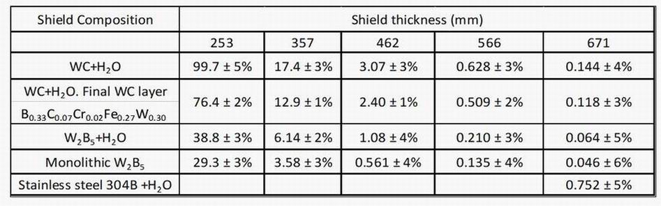
Another factor suggested previously [5] was that the tungsten carbide and water shield could be much
improved by just a single layer of borated material placed on the inside HTS facing layer of the shield where the
neutron energies are lower, and neutron absorption stronger. To check this, calculations were performed to find
the HTS power deposition with iron-tungsten borocarbide B0.329C0.074Cr0.024Fe0.274W0.299 placed in this position
within a WC and water layered shield. The results are shown in table 2 which confirms the appreciable
reduction of the borated inner layer shield compared with the WC and water shield. The W2B5 shields with and
without water continue to have superior power depositions.
Table 2 also contains data for the 304B stainless steel shield material which contains around 1.1 atomic
percent of boron and a density of 7.8 Mg/m3. It is well characterized, readily available and widely used in the
nuclear industry. It is seen from the last row that both monolithic W2B5 and W2B5+H2O are more than an order
of magnitude more effective at reducing core heating for that particular design point than the 304B+H2O. The
neutron fluence half-attenuation distance through the shield is around 54 mm compared to the 35.5 mm of
monolithic W2B5.
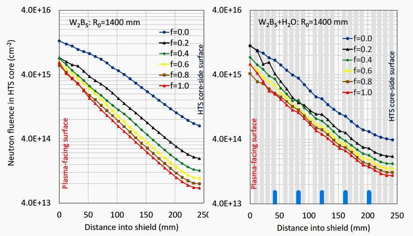
Table 2. A second practical consideration is whether it could be cost effective to increase the atomic concentration of
the absorbing isotope 10B. The results so far have been for the 20% atomic concentration of the absorbing
isotope 10B in natural boron. It is possible to create shield materials with an enhanced concentration of 10B [20].
This comes with additional cost [21,22], although this could be considerably mitigated if only say 40%
enrichment was required. Figure 13 shows the neutron fluence across W2B5 shields as a function of the fraction f of 10B in the shield without and with water content for major radius 1400 mm. It is seen that the fluence decreases considerably with increasing 10B isotopic concentration. Much of the possible gain is achieved by 40% isotopic fraction with higher concentrations having a more marginal effect. The water moderation appears to increase the neutron fluence at all radii except in the case of zero 10B isotopic concentration. The positions of the water layers are shown by vertical blue lines along the radius axis, and some effects are reflected in the corresponding fluence. The effects of increasing the 10B isotopic concentration seems to be greater for the monolithic shield than for the water moderated shield.
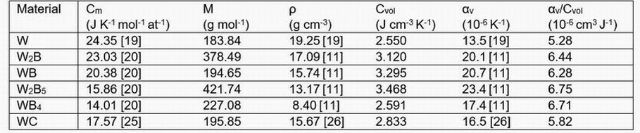
Figure 13. A further practical problem arises from the thermophysical properties of the candidate materials as shown in
Table 3. The molar heat capacity at room-temperature, Cm is taken from Refs [23-25]. Cm of WBx compounds decreases with increasing boron content. The values of Cm are converted into the volumetric heat capacity Cvol
using:
Cvol = Cm.ρ.n/M
where ρ is the density, M is the molar mass and n is the number of atoms in the formula unit. The ρ of the W-B
compounds showed notable variation in the literature. For example, as shown in table 1 the ρ of WB4 is given as
8.4 g cm-3 by [11] and 10.2 g cm-3 by [16], which could be due to variations in sample porosity. To avoid such
variability, the values for the borides are selected from only one source reference [11], for consistency. Cvol
generally shows the opposing trend to Cm with respect to boron content (with the exception of WB4) i.e. W2B5
has the highest Cvol of any of the candidate materials. This result is likely due to the higher atomic packing
density in W2B5 compared to monolithic W as shown in Figure 2.
Cvol, the heat capacity, can be related to the anticipated thermal strains by defining a simple figure of merit, the
expansion per unit energy, αv/Cvol which describes the amount of volumetric expansion per unit of thermal
energy absorbed. αv is taken from refs [17,10,23]. NB: this figure of merit neglects heat exchange with the
environment, which was necessary as thermal conductivity data are not available for the tungsten borides.
Table 3. Despite W2B5 having the largest Cvol, which tends to decrease αv/Cvol, this is more than offset by its large αv.
Thus, the value of αv/Cvol is greatest for W2B5. This means it will undergo the highest amount of thermal
expansion for every joule of thermal energy absorbed, while pure W will undergo the least expansion. This
suggests that thermal strain in W2B5 may be significantly higher than in W, which may lead to higher thermal
stresses.
The high thermal strain of W2B5 is exacerbated by its very impressive power absorption capability, as shown
in the MCNP calculations. Thus, the expansion for a given neutron fluence is expected to be even more stark
than the comparisons shown in table 3, suggesting that that the thermal stresses in a W2B5 shield will be
significantly higher than with monolithic W. This underlines the importance of assessing the thermal stress
resistance of candidate tungsten boride shields in future work.
Perhaps the most important practical consideration is the manufacturing capability to produce the tonnes of
shielding material needed for a fusion reactor. W2B5 is available in research quantities from several suppliers,
but not yet for tonnage quantities.
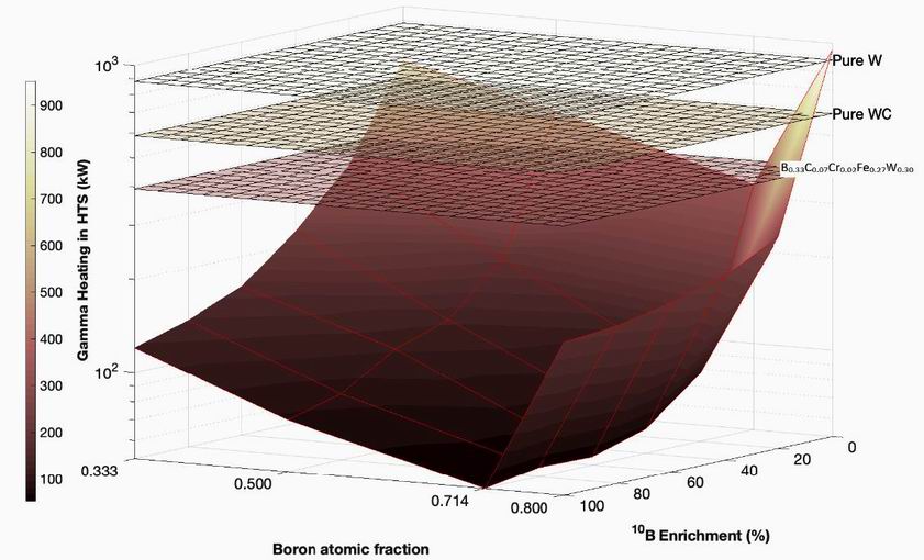
6. Conclusions Figure 14 graphically summarises the results of 10B enrichment and boron content with a 3-dimensional surface
of gamma power deposition as a function of both parameters. The plot illustrates the local minimum power
deposition for W2B5, shown previously in Figures 4, 6 and 12, is maintained at all 10B enrichment levels. It also
shows that the optimal material, i.e. W2B5 with 60% 10B or more, shows a factor of ~20 lower gamma power deposition compared to monolithic W.
Figure 14. It was previously thought that a hydrogenous moderating material, such as water or a metallic hydride, was
an essential part of any tokamak shield, reducing the power deposition and neutron and gamma fluences. This
paper shows that an alternative shield employing light atoms such as boron (Z=5) or carbon (Z=6) can be
equally as effective, and in the case W2B5, even more so. Boron introduces a third factor, neutron absorption, as
its absorption cross section rises with decreasing neutron energy.
This paper shows that increasing the shield's boron content generally decreases the power deposition to a
factor of 10-20 below that of monolithic tungsten, depending on the 10B content, suggesting that increasing
neutron moderation and absorption within the shield is a key factor. The trend then reverses between W2B5 and
WB4 deposition, probably because of the low density of WB4 and its relative lack of gamma attenuating
tungsten. Our study also shows that a monolithic W2B5 shield far outperforms previously-considered shield
architectures composed of outer WC layers and inner borocarbide layers [5].
Energy spectra of the neutron fluence through a W2B5 shield at R0 =2200 mm suggest that, with this boron
fraction, the energy spectrum of inelastically scattered neutrons is almost independent of distance into the shield
and attenuates through the shield at much the same rate as the elastically scattered fusion neutrons.
The conclusion is that W2B5 provides an optimal tokamak shield with its good compromise between gamma
shielding, neutron moderation and neutron absorption. At the same time, this study also highlights that the
candidates with the best shielding capability are also susceptible to the highest thermal strains. Further
understanding of their thermal and mechanical properties, and their evolution under radiation damage, is
therefore needed. The activation results for the same shield materials and configuration made using the
FISPACT code using neutron fluxes from this study will be presented in subsequent work.
References [1] Windsor C G 2019 Can the development of fusion energy be accelerated? An introduction to the proceedings
Phil. Trans. R. Soc. A 377 20170446
http://dx.doi.org/10.1098/rsta.2017.0446
[2] Windsor C G, Connor J, Janeschitz G, Windridge M and Whyte D (Editors) 2019 Fusion energy using
tokamaks: can development be accelerated? Phil. Trans. R. Soc. A 377 Issue 2141
https://royalsocietypublishing.org/toc/rsta/2019/377/2141
[3] Sykes A, Costley A E, Windsor C G, Asunta O, Brittles G, Buxton P,
Chuyanov V, Connor J W., Gryaznevich M P, Huang B, Hugill J, Kukushkin A,
Kingham D, Morgan J G, Noonan P, Ross J S H, Shevchenko V, Slade R, and Smith G, 2017 Compact Fusion Energy based on the Spherical Tokamak Nucl. Fusion 58 016039
https://iopscience.iop.org/article/10.1088/1741-4326/aa8c8d/meta
[4] Windsor C G, Morgan J G and Buxton P F 2015 Heat deposition into the superconducting central column of
a spherical tokamak fusion plant Nucl. Fusion 55 023014 https://iopscience.iop.org/article/10.1088/0029-5515/55/2/023014
[5] Windsor C G, Morgan J G, Buxton P F, Costley A E, Smith G D W and Sykes A 2016
Modelling the power deposition into a spherical tokamak fusion power plant Nucl. Fusion 57 036001
https://iopscience.iop.org/article/10.1088/1741-4326/57/3/036001
[6] Windsor C G and Morgan J G 2017 Neutron and gamma flux distributions and their implications for radiation damage in the shielded superconducting core of a fusion power plant Nucl.Fusion 57 116032
https://iopscience.iop.org/article/10.1088/1741-4326/aa7e3e
[7] Humphry-Baker S A, Marshall J M, Smith G D W and Lee W E 2017 Thermophysical properties of Co-free
WC-FeCr hardmetals 19th Plansee Seminar, at Plansee, Austria https://www.researchgate.
net/publication/318708043_Thermophysical_properties_of_Co-free_WC-FeCr_hardmetals
[8] Windsor C G, Marshall J M, Morgan J G, Fair J, Smith G D W, Rajczyk-Wryk A and Tarrago J M 2018
Design of cemented tungsten carbide and boride-containing shields for a fusion power plant Nucl. Fusion 58
076014 https://iopscience.iop.org/article/10.1088/1741-4326/aabdb0
[9] Humphry-Baker S A and Smith G D W, 2018, Shielding materials in the compact spherical tokamak Phil.
Trans. R. Soc. A 377: 20170443. http://dx.doi.org/10.1098/rsta.2017.0443
[10] Werner C J et al 2018 MCNP Version 6.2 Release Notes Los Alamos National Laboratory Report LA-UR-
18-20808
https://permalink.lanl.gov/object/tr?what=info:lanl-repo/lareport/LA-UR-18-20808
[11] Gauthier M (Ed.) 1995 Engineered Materials Handbook Desk Edition, ASM International 9639 Kinsman Road Materials Park, OH 44073-0002, USA
https://doi.org/10.31399/asm.hb.emde.9781627082006
[12] Athanasakis M, Ivanov E, del Rio E and Humphry-Baker S A 2020 A high temperature W2B-W composite
for fusion reactor shielding Journal of Nuclear Materials 532 152062
https://doi.org/10.1016/j.jnucmat.2020.152062
[13] Marshall J M, Walker D and Thomas P A 2020 HRXRD study of the theoretical densities of novel reactive
sintered boride candidate neutron shielding materials Nuclear Materials and Energy 22 100732
[14] Marshall J M 2018 EP3401413A1, An iron tungsten borocarbide body for nuclear shielding applications
https://doi.org/10.13140/RG.2.2.34460.13447
[15] Prokopec R, Fischer D X, Weber H W and Eisterer M 2014 Suitability of coated conductors for fusion
magnets in view of their radiation response Supercond. Sci. Technol. 28 014005
https://iopscience.iop.org/article/10.1088/0953-2048/28/1/014005
[16] Brookhaven National Nuclear Data Center, Evaluated nuclear data file
https://www.nndc.bnl.gov/exfor/endf00.jsp
[17] Duschanek H and Rogl P. 1995 Critical Assessment and Thermodynamic Calculation of the Binary System
Boron-Tungsten (B-W). Journal of Phase Equilibria 16 No. 2 199
https://doi.org/10.1007/BF02664852
[18] Lassner E and Schubert W-D 1999 Tungsten: properties, chemistry, technology of the element, alloys, and
chemical compounds Boston Springer https://doi.org/10.1007/978-1-4615-4907-9
[19] Blinder A V and Bolgar A S 1991 Specific heat and enthalpy of borides of transition metals in a wide
temperature range Poroshkovaya Metallurgiya 12 72-76
https://inis.iaea.org/search/search.aspx?orig_q=RN:24026107
[20] Chkhartishvili L, Tsagareishvili O, Gabunia D, January 2012, 10B-based materials for neutron shielding, 1st Int.
Conf. Modern Technologies and Methods of Inorganic Materials Science Tbilisi, Georgia
10B-based_materials_for_neutron-
shielding/link/560ffca708ae6b29b49a8ca9
[21] Wang YB, Pei G, Jiang D J,and Zhou M S, 2020, Economic estimation of boron isotope production by gas
diffusion method using BF3 as processing gas J. Phys.: Conf. Ser.1696 01200
https//iopscience.iop.org/article/10.1088/1742-6596/1696/1/012006/pdf
[22] Wiedenmann D and Cook K S, 2020, The Benefits of Using Enriched Boric Aid in Commercial Nuclear Power
Plants, 3M Technical Ceramics, Inc., USA, Technical Paper Submission Number: 10221,
https://multimedia.3m.com/mws/media/958426O/3m-enriched-boric-acid.pdf
[23] Cambridge Isotope Laboratories Inc, 2021, Product B-10 Metal
https://shop.isotope.com/productdetails.aspx?itemno=BLM-1546-PK
[24] Andon R J L, Martin J F, Mills K C and Jenkins T R 1975 Heat capacity and entropy of tungsten carbide
Journal of Chemical Thermodynamics 7 1079-1084
https://doi.org/10.1016/0021-9614(75)90241-4
[25] Kurlov A S and Gusev A I 2013 Tungsten carbides: structure, properties and application in hardmetals
Cham Springer https://doi.org/10.1007/978-3-319-00524-9