The rank of stopped diapason pipes
It started sadly. One of our organist friends from Upton died suddenly. We sang
every week with his wife, and one day as she was clearing out her loft she said,
"Would I like to have a set of old organ pipes?" When she brought
me one and I had a blow on it, it started with a nice "chuff" and carried on with
the soft woody sound of good chamber organs. It was a wooden stopped diapason:
you could tell its age from the nice cursive script that graced some of
the pipes. I was inspired!
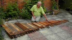 Fortunately an advert in the
"Electronic Organ Constructers Society"
magazine enabled me to buy a set of similar pipes for spares.
These pipes had the traditional organ range from C, two octaves below middle C,
to f3, two and a half octaves above. Some definitions of the C's
are given in the table below, adapted from
Wikipedia
| Frequency | Helmsholtz | Scientific | ABC | Octave | Wavelength | Open length | Closed length |
| cycles/sec | notation | notation | notation | name | mm | feet | feet |
| 65.407 | C | C2 | C, | Bass | 2623 | 8' | 4' |
| 130.813 | c0 | C3 | C | Tenor | 1311 | 4' | 2' |
| 261.626 | c1 | C4 | c | Middle | 656 | 2' | 1' |
| 523.352 | c2 | C5 | c' | Soprano | 328 | 1' | 6" |
| 1046.502 | c3 | C6 | c'' | Top | 164 | 6" | 3" |

The physics of stopped diapason pipes
The speed of sound in air: V=343.2 metres per second, is pretty fast, ~3 seconds for a kilometre, but musical frequencies
are pretty high.
 Middle C is f=261.6 cycles per second, for the standard tuning of A=440. Sound is a wave,
and the wavelength for middle C is l=V/f=1312 mm.
The figure above shows how the pressure or amplitude of the sound wave changes with either time or space. It moves
along a sine wave which starts at a high positive amplitude, goes through zero to a negative amplitude,
and then back again to its starting amplitude.
In a stopped pipe, the amplitude at the stopped end must be zero, while
the amplitude at the fipple end is large. The length of the stopped pipe is then just one quarter of a wavelength,
or about one foot for middle C. The figure on the right shows the middle C pipe from the set against a foot ruler.
 Air blowing over the fipple creates turbulence with periodic pressure variations. The sound from these travels
down the pipe, is reflected from the stopped end, and returns to the fipple. It the length of the pipe is such that
the round trip time corresponds with the frequency, then the pipe resonates or sounds.
If the pipe is "open", then the pressure variation at its end will be high and the pipe will be twice as long
for the same resonant frequency. But open pipes tend to have more harmonics and give a less sweet tone that the
pure flute-like tones from the stopped pipes.
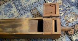
The important fipple part of the pipe is shown taken apart for the lowest pipe on the organ C.
The air comes in through the tube on the right, rises up to a thin "airway", which tapers at the upper
end to produce a wide jet of air directed at the "labium" - the sharp edge of wood placed a centimetre
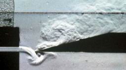
or so away from the end of the jet. The photo to the right shows the air stream which
provides the stimulus for the resonant sound.
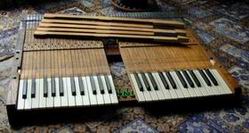
The old Binns keyboard from Streatley Church
This was a work of art in itself. Our tuner said that Binn's organs were built like a battleship.
Although over 100 years old there were no signs of wear.
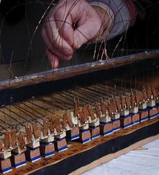
 Their alignment is from one pin near their centre, with the red felt washer, and one pin
under the key itself with the blue washer. The keyboard structure was just 800 mm across and 740 mm deep and this
determined the size of the organ frame.
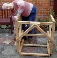
The oak organ frame from the forest of Belleme
So often organs are wrapped up in beautiful cases. Until you open a door and have a look inside
the case you have no idea what is going on when you press a key. Peering round
inside the organ, you see all the pipes but they sit above a big windchest and that too
is tightly closed. The very place where the
action that makes the pipe sound is placed is opaquely screwed up tight!
I determined to make an organ without any case where all the pipes and all the action
would be visible. I would make a windchest with perspex sides so that you could see what
was happening within its walls.
By a lucky chance a good friend who lived near our French house in Belleme came round
one evening with a whole load of lengths of rectangular section oak. Actually they were
rejects from the local wood-yard. They were really for firewood, but there were enough good
lengths there for me to plan the whole frame of the organ.
The large flat surfaces of 1" oak veneer used for the base of the treadle board.
the reservoir chest, the top and music stand also have a history. They came from the wardrobe
doors of the three-piece suite I had as a 10-year old. They had had a 60-year use and it was touching
to use them again.
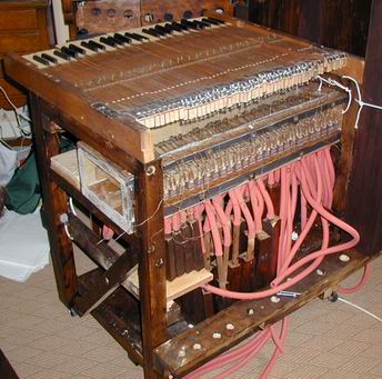
The simple action possible with a single rank organ
The average spacing of the keys on a standard keyboard is around 13.5 mm. The widths across our pipes
are always larger than this - from 17 to 125 mm. The conventional action for traditional organ construction is
to make up a "roller board" that mechanically spreads out the action at the keys to the required spacing.
However if the keys are divided alternately into two sets, the average spacing of each set is
27 mm. This is sufficient wide for 19 mm outside diameter soft rubber pipe to be used for the airflow
to the pipes and that is the solution used here. The figure to the left shows the keyboard, and the wire
connections into the windchest beneath the keyboard. Their are two rows of red flexible rubber pipes.
 The 16 largest pipes from C to e0 are held vertically
along the back and left side. They are blown by quite long rubber pipes connected to the
windchest. Most of the other pipes simply hang upside down from short rubber tubes
underneath the windchest.
The windchest and palettes
The windchest is the central processor of a pipe organ. As each note key is pressed a stream of wind is sent
to the appropriate pipe. This is done by a soft leather-coated "palette" being moved
to let the air out through a hole beneath it. The whole windchest is fed with air from a blower:
it needs to be leak-tight!
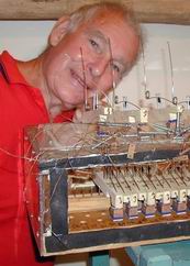
This organ has only the single rank of pipes so that each palette opens a single hole feeding a single pipe.
The figure to the left shows the construction of the palettes. Vertical alignment is by a simple nail hammered into
the back of each palette which enters into the set of horizontal holes drilled in the back wall of the windchest.
Horizontal alignment is by a set of vertical upturned nails which travel inside holes drilled in each palette.
The cup-hooks screwed into the end of the palette
were connected through leather thongs to the wires from the keyboard.
The top and the front of the windchest were all made from 3 mm thick perspex sheet - making all the
action nicely visible. A tricky point was the line of holes along the top front where the action wires passed out
of the windchest. About 0.6 mm enamelled copper wires were used, and these passed through 1 mm holes drilled
in a strip of oak. It initially lost air, and small leather washers with a needle-point hole were needed to stop the leaks.
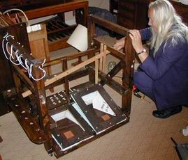
The foot and hand-operated bellows
Mo was always keen on a non-electric human-powered organ - common enough on pipe organs long ago.
Direct action was used with the foot placed on the slope of the bellows. The cladding was held down
by a perspex cover that enabled you to watch the leather valves flapping.
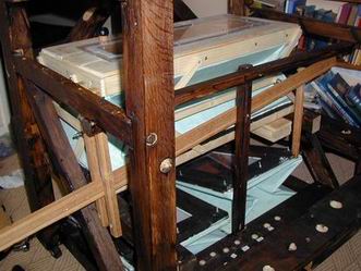 But not all organists can cope with that sort of pedelling, so a back-up hand
operation seemed a good idea. A simple lever pivoted at the organ centre enabled the up and down
motion pf the two bellows to be duplicated by hand or foot. This process removed the springs conventionally
used to bring the bellows up again after each depression. Of course the two bellows do not work independently,
but this has been no problem in practice.
The air reservoir
Especially with a bellows system it is important to have an air reservoir to stabilise the air pressure
while the bellows operates and while different numbers of keys are pressed. The reservoir was much easier to
make than the bellows, and was quite large, about 650 x 270 x 160 mm in size. The large size is essential
to supply the extra air when you play the bass notes for any length of time. The heavy wood frame provides the
necessary constant pressure. A small weighted valve guarded against excess pressure.
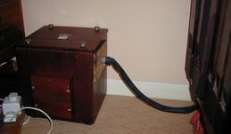
The electric air pump
The foot or hand pumping worked OK but were both hard work!
I tried hard to make a pump. Mark I used the motor from a 50 watt variable speed fan
found in a skip outside Durham cathedral with a home-made wooden rotor. It was quiet and blew the bass pipes
rather well, but it did not blow the smaller pipes. Mark II came from Ebay.
It was cheap and small but rather noisy even when encased in a wood and cotton felt container.
So I bought Mark III: a reconditioned Discus Wren from Watkins and Watson. It was by far the biggest item
in the organ budget, but they gave me a good deal and it has proved excellent! Hear it for yourself!
Copyright 2011 Colin Windsor : Last updated 16/6/2013
 Middle C is f=261.6 cycles per second, for the standard tuning of A=440. Sound is a wave,
and the wavelength for middle C is l=V/f=1312 mm.
The figure above shows how the pressure or amplitude of the sound wave changes with either time or space. It moves
along a sine wave which starts at a high positive amplitude, goes through zero to a negative amplitude,
and then back again to its starting amplitude.
In a stopped pipe, the amplitude at the stopped end must be zero, while
the amplitude at the fipple end is large. The length of the stopped pipe is then just one quarter of a wavelength,
or about one foot for middle C. The figure on the right shows the middle C pipe from the set against a foot ruler.

 Air blowing over the fipple creates turbulence with periodic pressure variations. The sound from these travels
down the pipe, is reflected from the stopped end, and returns to the fipple. It the length of the pipe is such that
the round trip time corresponds with the frequency, then the pipe resonates or sounds.
If the pipe is "open", then the pressure variation at its end will be high and the pipe will be twice as long
for the same resonant frequency. But open pipes tend to have more harmonics and give a less sweet tone that the
pure flute-like tones from the stopped pipes.
The important fipple part of the pipe is shown taken apart for the lowest pipe on the organ C.
The air comes in through the tube on the right, rises up to a thin "airway", which tapers at the upper
end to produce a wide jet of air directed at the "labium" - the sharp edge of wood placed a centimetre
or so away from the end of the jet. The photo to the right shows the air stream which
provides the stimulus for the resonant sound.


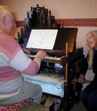
 Fortunately an advert in the
"Electronic Organ Constructers Society"
magazine enabled me to buy a set of similar pipes for spares.

 Their alignment is from one pin near their centre, with the red felt washer, and one pin
under the key itself with the blue washer. The keyboard structure was just 800 mm across and 740 mm deep and this
determined the size of the organ frame.

 The 16 largest pipes from C to e0 are held vertically
along the back and left side. They are blown by quite long rubber pipes connected to the
windchest. Most of the other pipes simply hang upside down from short rubber tubes
underneath the windchest.


 But not all organists can cope with that sort of pedelling, so a back-up hand
operation seemed a good idea. A simple lever pivoted at the organ centre enabled the up and down
motion pf the two bellows to be duplicated by hand or foot. This process removed the springs conventionally
used to bring the bellows up again after each depression. Of course the two bellows do not work independently,
but this has been no problem in practice.
