
HNBFC/75/P16 (1975)
A Discussion Paper for the Exploitation of the New Harwell LINAC for Condensed Matter Studies
C. G. Windsor and R. N. Sinclair A.E.R.E., Harwell, Oxon,Summary
In December, 1974, Harwell obtained approval for the construction of a new electron LINAC able, to give improvement factors of around an order of magnitude over the present LINAC. The project was funded by Nuclear Physics Division but shared use, as on the present LINAC, is envisaged with the electron beam multiplexed between nuclear physics targets and a new condensed matter cell having some 18 beam holes. The project and its time scale is described, and figures detailed for the expected fluxes at the spectrometer positions assuming 50% multiplexed use. We show here that, for epithermal neutron energies (0.2 to 1.0 eV), both calculation and extrapolation from experimental results on the present LINAC suggest that the, performance of spectrometers on these holes can exceed that from hot source holes at the ILL, or indeed that from any other source at present operating or approved in the western world. We therefore conclude that provision should be made for a substantial portfolio of instruments on the new LINAC. We present here a possible portfolio of 9 instruments to be installed over 10 years, the scientific programmes that would be possible with them, and their approximate costs of construction (or moving from their existing positions), and installation. We also give outline information and approximate costs of an appropriate experimental hall, and of the laboratory and office accommodation needed. We emphasise that the plans outlined merely form a basis for discussion and call for comments from the community of neutron beam users.
The references quoted are contained in the collection of references on Condensed Matter Research Using Pulsed Neutron Sources, D. F. R. Mildner and G. C. Stirling. RL-75-095.
CONTENTS
2. The new Harwell LINAC Project
3. The specification of the new LINAC
4. The expected neutron fluxes at the moderator surface
5. The expected neutron fluxes at the specimen position
6. Comparisons with reactor performance
7. The Condensed Matter Target cell
9. A possible choice of instrument priorities
Appendix
1. The Total Scattering Sepctrometer (TSS)
2. The Back Scattering Spectrometer (BSS)
3. The Inelastic Rotor Spectrometer (IRS)
4. The Crystal Analyser Spectrometer (CAS)
5. The Cross-Section Spectrometer (CSS)
6. The Constant Q Spectrometer (CQS)
7. The Chemical Inelastic Spectrometer (CIS)
8. The High Pressure Spectrometer (HPS)
9. The Beryllium Filter Spectrometer (BFS)
Introduction
1. The advantages of using a pulsed electron LINAC as a thermal neutron source
for diffraction experiments were realised during the fifties (Egelstaff, 1953).
Compared with a reactor neutron beam pulsed by a convetnntional rotor system,
they give a relatively high epithermal neutron flux, relatively short pulse times,
allowing short flight paths, and relatively larged pulsed beam areas. The
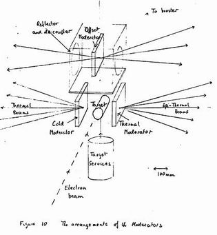
intrinsic neutron background should be less because the g and fast neutron
contributions come as a "flash" essentially when the LINAC fires and scarcely exist
between pulses when the slow neutron signal is being counted.
2. The present Harwell LINAC was installed in 1959 largely for nuclear
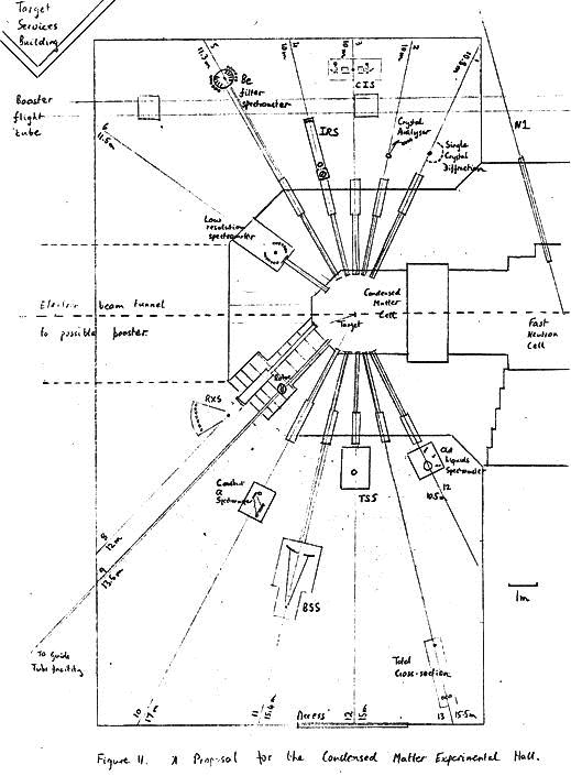
Physics purposes, but since 1967 there have been a number of condensed
matter experiments. Initially the programme was one of exploiting the
techniques possible using the LINAC, including neutron moderation (Day
and Sinclair, 1969 and Sinclair 1968) and spectrum calibration (Day, Johnson
and Sinclair, 1969). Later work in the nature of demonstration experiments
was performed on single crystal Mn5Ge3 (Day and Sinclair. 1970) and on
inelastic molecular spectroscopy (Day and Sinclair, 1971). In 1971 the
work aquiared new impetus with ths commissioning of the Total Scattering
Spectrometer (TSS). This spectrometer rapidly acquired an appreciable
joint SRC/Harwell programme in the field of structure factor measurements
from liquids and amorphous solids at high scattering vectors Q. The
programme was reviewed by an NBRC Working party chaired by Dr Clark in 1973
(NBR p. 201). This group recommended further imporovements in the counter
assembly and in data handling which have now been implemented. The present
programme has been recently reviewed (Sinclair et al, 1974). Experiments
have been performed on the gases nitrogen and oxygen (Page and Powles 1975),
the liquids nitrogen and oxygen (Clarke et al, 1975), heavy water, phosphorus,
bromine (Clarke et al, 1975). gallium and carbon disulphide molten
polymer polytetrafluoroethylene, the amorphous materials silica and germania
(Wright and Sinclair, 1975) as well as several powder spectra. The nitrogen
work is gratifying in giving possibly the first published example of a
problem where measurements to comparable accuracy and resolution have not
been possible on any reactor including the Grenoble reactor with its hot
source.
3. There has also been successful experimental programmes on other electron
LINACS of comparable power. These include the Rensselaer Polytechnic
institute, USA, LINAC where several inelastic experiments have oeen performed
(e.g. Kironac et al, 19670;Pan and Webb, 1985), the Tohoku LINAC in Japan
where there exists a complex of 8 beam holes covering both elastic and
inelastic spectrometers (Euratom 1973), and a smaller inelastic programme
at Toronto, Canada (Egelstaff et al, 1975).
4. We must also review the status of other projects for the production of
pulsed neutrons other than by the electron LINACS (see Hobbis 1974). Other
processes which might be used are fission, proton spallation and fusion.
All these methods have the intrinsic advantage that they produce less target
heat to be dissipated per neutron produced. The heat produced from electrons,
fission, protons and fusion are respectively 2000. 100, 40 and 17 MeV per
neutron produced The fission process may be exploited either in a pulsed
reactor or a sub-critical neutron booster. The pulsed reactor IBR 30 at
Dubna, Russia, has operated for some years (Alberquerque, 1969) and has a
peak thermal flux of
1014ns-1cm-2.
However its long pulse time of 90 mseconds
has meant the use of very long flight paths with consequently reduced
count rates, not to mention instrumental costs. The project IBR 2 should
give an impressive x100 performance with
1016ns-1cm-2 peak thermal fluxes.
These long pulse-times are avoided by the sub-critical boosters as
existing for a nuclear physics programme on the LINAC at Harwell (Poole and
Wiblin, 1958). Used on the new Harwell LINAC a booster giving a
multiplication factor of order 50 can be constructed without damaging pulse
lengthening or background from delayed neutrons between pulses. Such a
project is being discussed at Oak Ridge as part of the ORELA electron LINAC.
Larger multiplications are possible using mechanically modulated boosters
as in the "Super-booster" project (Poole, 1967) but at much greater cost
and complexity.
Proton spallation sources give short intense neutron pulses with less
problems in heat dissipation. The ZING project proposed by Argonne National
Laboratory in 1972 (Carpenter and Marmer 1972) would have provided
1015ns-1cm-2
peak fluxes. This proposal has now been superseded by a more ambitious project,
IPNS, which will use the new proton synchrotron to give peak neutron fluxes of
1016ns-1cm-2
(Carpenter and Price, 1975). Already, prototype ZING-P
experiments have been carried out at Argonne with peak fluxes of around
1013ns-1cm-2.
Elastic experiments on several powder and amorphous samples
(Beyerlein et al, 1974, Beyerlein et al, 1975), and inelastic measurements on
molecular vibrations in hydrogenous compounds (Mildner, Private Communications)
have been completed with results showing great promise for the larger machines.
Laser fusion sources are necessarily pulsed and have the desirable
characteristic of relatively long periods between pulses. Their progress
must be awaited eagerly in any consideration of an ultimate pulsed source.
The New Harwell LINAC Project
5. The project for a new LINAC at Harwell obtained its impetus from the
Nuclear Physics Division. They wished to replace the existing one with one
representative of the best technology of proven reliability that was
available "off the shelf". The machines considered were L-band (1300 MHz)
LINACS built by Radiation Dynamics of Swindon, which are available in
modular form in up to four modules. The machine originally considered was
a 2 module machine capable of delivering an electron power of order 40 KW
to a target. Assuming a 50% multiplexed use for condensed matter use this
would have given a mean flux gain of around 5 over the present LINAC,
6. The proposal was considered in detail by the LINAC working party chaired
by Dr. Hobbis (NBR/LRG/75, P.7). This considered the experimental
programme possible with LINACS, the likely portfolio of spectrometers which
could be justified, and attempted the complex task of making fair comparisons
between LINAC and reactor performance. It appeared that in the field of
epithermal energy neutrons (0.2 - 1 eV) where the fast pulse times from the
LINAC could he exploited, even the present LINAC was competitive with
reactors (LIWP/P.8). In the case of liquid studies where back scattering
can be exploited, the existing LINAC actually out-performed the hot-source
at Grenoble at short wavelengths <0.5AMS, (LIWP/P.9). Studies for a high
relolution (Dd/d = 0.03) Back Scattering Powder Spectrometer (LIWP/P.4) and
an inelastic rotor spectrometer (LIWP/P.3) appeared feasible using the
present LINAC and programmes to implement these spectrometers have now gone
forward (NBR/LRG/75/P.4, HNBFC/73/P.2). It was felt that in some respects
the Harwell proposal was over-modest and that appreciable SRC investment
should centre around a more powerful LINAC.
7. The proposal finally approved by the treasury in December 1974 was
for a four module LINAC giving 90 KW beam power which in 50% multiplexed
use would give order of magnitude gains in the condensed matter counting
rates. The time-scale for the project is outlined in figure 2. The new
LINAC is expected to be operational in the Spring of 1976. By phasing the
building construction it was possible for the present LINAC, including
condensed matter work on cell II, to be continued until the end of 1976.
Of the major components noted, the condensed matter target cell is the most
critical and has to be defined by the end of May 1975. This is being done
through a discussion group of present users held at Harwell. The LINAC, the
target cells and targets are being funded solely by Harwell. This part of
the work is under the control of the Project Officer, Dr. Eric Lynn of
Nuclear Physics Divison, with the help of a Project Management Committee
(LAPMC) and a Technical Advisory Committee (LATAC). The target hall of
the condensed matter facility, the instrument protfolio and their associated
support facilities have not yet been defined or funded.
The Specification of the New LINAC
8. The general arrangement of the new LINAC is shown in figure 3. It
fires from the north side at right angles to the existing LINAC so that the
existing Nuclear Physics booster and its associated flight tubes might
remain unchanged by bending the electron beam by 900 and slightly downwards
to join the beam line of the existing LINAC. Down the new LINAC beam line
in the position formerly occupied by cell III would be a Fast Neutron Target
for nuclear physics use and the Condensed Matter Cell. A Low Energy Cell
would be placed after 2 LINAC sections for 7-30 MeV electron irradiation
work.
9. The detailed specification of the new LINAC has been given in LATAC/75/
P.2. Its minimum performance as given by the acceptance tests is only
slightly inferior. Run in an "open circuit" condition with negligible beam
power, the accelerator gives its full electron voltage of 136 MeV. At the
higher beam powers needed for condensed matter research the output voltage
drops following the "load line" given in figure 4. The acceptance test
confirming this important curve is that for 0.75A pulse current the voltage
should be at least 72 MeV. within the constraint of the load line there is
considerable flexibility in choice of pulse repetition frequencies and
pulse times. Standard pulse repetition frequencies are 150, 300, 600 and
1200 p.p.s. and standard pulse lengths for condensed matter use of 0.4, 1, 2
and 5 mseconds.
10. Linac pulses can be switched or muliplexed between the booster, the
low energy cell and either the fast neutron cell or the condensed matter
cell. (Provision for multiplexing between these two cells can be made at
a later date). Pulse length modulation is possible so that short pulses to
the booster and long pulses to the condensed matter cell are feasible. At
present pulse current modulation is not possible so that the low pulse
currents appropriate to the long pulse condensed matter experiments will
embarrass multiplexing with the very short pulses required by the low energy
cell and fast neutron cell who could use much higher currents of order 6A.
Because of these points non-multiplexed sole usage is expected during the
fast neutron cell operation.
11. Some of the multiplexed modes of operation which are envisaged for
routine use have been given by Lynn in LATAC/75/P.4. The most important
for condensed matter usage are as follows.
| - | Multiplexed Cells | Frequency | Pulse Current | Pulse Length | Electron Energy | Power |
| - | - | p.p.s. | A | msec | MeV | KW |
| (a) | Condensed Matter Cell | 150 | 1 | 5 | 60 | 45 |
| - | Booster | 150 | 1 | 0.1 | 127 | - |
| (b) | Condensed Matter Cell | 300 | 1 | 2 | 60 | 36 |
| - | Booster | 300 | 1 | 0.1 | 127 | - |
| (c) | Condensed Matter Cell | 100 | 1 | 5 | 60 | 30 |
| - | Booster | 100 | 1 | 0.1 | 120 | - |
| - | Low Energy Cell | 100 | 1 | 5 | 20 | - |
| (d) | Condensed Matter Cell | 600 | 1 | 2 | 60 | 72 |
The choice of operating mode will always be a compromise between longer
wavelength users who can use long electron pulse lengths matching their
longer neutron thermalisation time and also require long periods to prevent
frame overlap, and shorter wavelength users for whom the reverse considerations
apply. In practice most of the present interests use neutrons in the range
1 to 0.5 AMS (a four-fold energy range) over which the neutron thermalisation
time varies between 7 and 35 msec. Thus mode (a) above with 5 msec pulses is
well matched to these times. Mode (b) would be suited to experiments
between 0.5 and 0.3 A. It will be noted that the reduced pulse time in
general compensates the increased pulse repetition frequency to leave the
mean power, and hence the count-rate, largely unchanged. Case (d) involving
safe use of the LINAC gives doubled beam power and might be advantageous
for a few experiments where short counting times were essential. In general
it gives no advantage over a multiplexed run (b) of twice the running time.
The Expected Neutron Fluxes at the Moderator Surface
12. When electrons of energy greater than around 30 MeV energy are stopped
in a natural uranium target fast (~ 1 MeV) neutrons are produced essentially
instantaneously from e -> g -> n reactions. The fast neutron flux produced
is proportional to power
nfast = 4.12ns-1KW-1 ... (1)
13. For condensed matter studies these neutrons must be moderated. This
process has been extensively studied (see Mildner's references). For a simple
30 mm. thick slab of polyethylene close to the target the flux of slow (>0.3AMS)
neutrons produced is again proportional to power with the mean thermal flux
at the surface of the moderator being of order
nthermal = 1.109ns-1cm-2KW-1 ... (2)
This number is not very meaningful since it depends somewhat arbitrarily
on the lower wavelength limit chosen, and since the spectrum is grossly
non-Maxwellian cannot be directly compared with reactor fluxes.
14. The wavelength dependent flux calculated for the new LINAC by scaling
from measurements made on the existing LINAC is sketched in figure 5. Here
we have assumed a 30 mm thick polyethylene target at ambient temperature
running in the multiplexed mode (a) of paragraph 11 where the beam power is 45 KW
just 10 times the beam power during multiplexed operation on the present
LINAC. The figure shows the roughly 1/l dependence of the flux for
epithermal neutrons with the typical Maxwellian peak becoming significant
above 0.6AMS. The mean flux in the epithermal region may be expressed in
round figures as
nmean(λ) =
2.1010/l(Ǻ)ĀĀ
n s-1 cm-2 Ǻ-1ĀĀĀ ģ(3) This figure is derived from the flux curve given in LIWP/73/P.2 where the
flux is given per (eV) on the epithermal energy range for the old LINAC as
n(E) =
1.109/EĀĀ n s-1 cm-2 eV-1ĀĀĀ In practice the spectrum shape is found to be a proportional to E-0.82,
but we ignore the difference for the present purpose.
The relationship between flux per AMS and flux per eV is given by
n(l)dl = n(E)dE.(dl/dE)
=n(E).(2E/l)dl =(1.0/E).109.(2E/l)dl
= (2.109/l) .dl The general relations-hip between fluxes in AMS and eV units is
n(l) =
n(E). 7 E3/2 The relationship between energy and wavelength being
l =
0.286/E1/2 15. The actual utility of these neutrons depends critically on the pulse
length of the moderated neutrons. This moderation time has again been well
discussed in the literature (Fluharty et al. 1969). For the present purposes
we shall simply take the observed pulse widths as measured on the present
LINAC. Again for 30 mm polyethylene and in the epithermal region we obtain
DTmod Ā= 7 (lǺ) msĀ
ģ(4) This dependence of the pulse time on wavelength is of fundamental importance
in understanding the performance of LINAC experiments. It has the simple
physical interpretation that as the neutrons slow down by inelastic
collisions within the moderator, the number of collisions required and hence
the time spread is proportional to the wavelength.
Within the Maxwellian region of the spectrum, the pulse times are
much longer, around double, because of the large number of nearly elastic
collisions suffered by the neutrons before being lost from the moderator.
The pulse shapes also become very asymmetric with a slowly decaying tail.
16. The pulse times and flux distribution associated with the epithermal
wavelength range can be extended into the thermal wavelength range by
preventing the build-up of the Maxwellian in this region. This can be done
by homogenous poisoning of the moderator by neutron absorbers (Day and
Sinclair, 1969), or by heterogeneous poisoning using a "cadmium sandwich"
technique to decouple a very thin thermal moderator from a much thicker
epithermal reflector layer. Both these methods produce some reduction in
the epithermal flux. The best method which avoids this disadvantage is to
cool the moderator so that the Maxwellian peak is shifted to the long
wavelength end of the spectrum. A liquid nitrogen cooled slab of
polyethylene is sufficient to extend the epithermal performance through the
1Ǻ region, and such a moderator will be installed on the present LINAC
this year.
17. Assuming the presence of such a cooled moderator for thermal studies
on the new LINAC we may take relationships 2 and 3 above to hold over the
whole range. The peak neutron flux may then be calculated assuming a pulse
repetition frequency f = 150 p.p.s. as in multiplexed use system (a) to
be given by
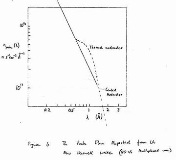
npeak(l) = [nmean(l)]/[f Dtmodsqrt2]= 2.1013/l2(Ǻ)ĀĀ n s-1 cm-2 Ǻ-1 Here we have assumed that the moderation pulse time is in all cases matched
to the electron pulse time so that the true pulse time is of order sqrt2 times
the moderation time. This relationship is plotted in figure 6 together
with dashed lines showing the more complex relationships existing within
an ambient and cooled moderator Maxwellian.
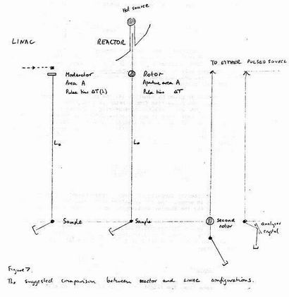
The Expected Neutron Fluxes at the Specimen Position
18. The peak fluxes given up are still not comparable with reactor fluxes
because the LINAC pulse has greater utility, being of larger area and
angular divergence than say the chopped beam transmitted by a rotor. The
valid comparison with reactor situations is between fluxes at the sample
position for configurations of comparable resolution, as suggested in
figure 7. By sample position in this connection, we generalise to refer
to the position of the next component of the instrument, be it a real
sample, a rotor, or a monochromating crystal.
If the LINAC or rotor time pulse length is DT, its effective area A
and the required wavelength resolution over the incident flight path L0 is
R = Dl/l = ĀDT/TĀ ģ(6) Then the incident flight time (T0) defines the flight path L0 from
L0 Ā= Ā(h/ml) T0 = (h/ml). DT/RĀ
ģ(7) The time average flux at the sample position is therefore
Nsample(l) = nmean(l)[A/4pL2] = nmean(l)[m2l2R2]/[4ph2].[A/ DT2] ģ(8) This is an important result, and the bracketed part may be said to define
a "figure of merit" for pulsed sources. Short pulse times improve fluxes
at the specimen position at least as DT-2. In practice it is often more
extreme than this as long pulse times also imply long flight times T0 giving
frame overlap problems and, of even more importance, the expense of long
flight path instruments.
19. Because as given by equation (4) the pulse time increases proportionally
to A, while the pulse time from a rotor is independent of A, the comparison
between a LINAC and a reactor time-of-flight spectrometer will always
suggest 1/l2 dependence in any relative difference between LINAC and reactor.
Thus the new LINAC may have a moderator area A = 20000 mm (~15 x 15 cm2)
and an overall pulse time AT = 10(x8) S. A typical Harwell rotor as used
on 6H in DIDO has a rotor aperture A = 1000 mm2 (1" x 2" with 75%
transmission), and a pulse time DT = 20 mS. The relative figure of merit
is therefore
nLINAC/nreactor = (20000/1000).(20/10l)2) = (80/lǺ )2 ĀĀģ(9) Nsample(l) = nmean(l)[A/4pL2] Thus LINAC/reactor comparisons based on peak fluxes can be two orders of
magnitude in error. The l-2 variation also shows the inherent advantage
of LINACS for the shorter wavelength end of neutron beam science.
20. We next evaluate the time average flux at the sample position given
the above values for the moderator area A and the overall pulse time AT,
and assuming the mean flux distribution given by equation 3. Substituting
in equation 8 and remembering that
we obtain for the time-average flux at the specimen position
~ (2.1010/l) R2/l2(Ǻ)ĀĀ n s-1 cm-2 Ǻ-1ĀĀ Āģ(10) At the same time, the flight path L is given from equation 7 as
l0=[4/ l].[10 l/R]=40R
mm,ĀĀĀĀĀĀĀĀĀĀĀĀĀĀĀ ģ(11) and the incident beam collimation alpha0 is given by
a0= A1/2/L0Ā rad = 200R0ĀĀĀĀĀĀĀĀĀĀĀĀĀ ģ(12) In many cases it is more meaningful to discuss the mean flux per wavelength
resolution element D l. This is related to the flux per Ǻ through
Then the incident flight time (T0) defines the flight path L0 from
nres(l) = d(l).dl = n(l).Rl = 2.1010R3 ns-1cm-2
In the table we tabulate these quantities as a function of resolution.
It should be noted that the flight path length and incident collimation
do not depend on wavelength and hence can be uniquely determined as a
function of resolution. In terms of the suggested sizes of the new
LINAC target cell and building, we may note that the 1% wavelength
resolution length of 4m lies within the cell wall (but could be employed
using the loose block hole 10 in figure 9). The 0.6% resolution distance
of 6 m occurs conveniently 1.5 m from the proposed cell wall and will give
a most convenient spectrometer position. The 0.3% resolution distance of
13 m occurs near the edge of the proposed building. The 0.1% resolution
distance of 40 m would necessitate a separate spectrometer building.
However for certain of the proposed holes (e.g. number 4) there is no
obstruction preventing flight paths even up to twice this figure.
21. For very long flight paths, the use of neutron guide tubes must be
considered. These have the.great advantage of giving good (>50%) transmission over
many tens of metres, but at the expense of an angular collimation angle a
determined by the guide tube material and the wavelength. For nickel guides
...(13)
Thus the guide transmission is proportional to lamba2 and favours long
wavelengths rather than the short wavelengths at which LINACS give their best
performance relative to reactors. For a guide tube configuration, the
analogue of equation 8 for the time average flux at the sample position is
nguide(l) = nmean(l)(ag2/4p)= 2.1010/(4pl).(0.2l/57)2 = 2.104l n cm-2s-1A-1 (14) Thus the time average sample flux is now independent of flight path and
increases relative to the simple geometry at a given distance as lamba2.
However for 1Ǻ neutrons the gain only occurs for flight paths greater than
about 40 m. For cold neutrons with l = 2Ǻ the guide tube has the useful
collimation of 0.4 0 and begins to show a nett gain even for 0.2% resolution
at a 20 m flight path. From equations 14and 12 it may be seen that the
l > 103 Ǻ ...(15)
Comparisons with Reactor Performance
22. It must be said that comparisons between LINAC and reactor performance
are never easy, and are subject to many uncertainties. The best comparisons
are between individually optimised spectrometers attempting to measure in
the same range with the same resolution. Such a comparison is described
in paragraph 14 but the completely different methods employed mean that the results
are less applicable to any general comparison between the neutron sources.
A second type of comparison, more valid, is a general comparison in which
LINAC time-of-flight experiments are compared with rotor time-of-flight
experiments using a reactor. Such comparisons are quite sensitive to the
details of the rotor system employed. There are two philosophies, neither
of which are satisfactory, One is to take the parameters from routinely
running rotor systems, often optimised for other wavelength ranges. The
other is to design the required rotor and assume that it can be made
routinely operational. (An important point of confusion here is to compare
plausible LINAC rotors with those required on reactors where g and fast
neutron stopping power are essential).
23. We now review and updata a discussion paper LIWP/73/P.8 which
attempted the comparison between LINACS and rotor systems on reactors
sketched in figure 7. It was assumed that to keep resolution and
constructional details comparable a rotor would be available giving a
pulse time DT comparable with the moderation time 7l mS from a LINAC. A
standard Harwell rotor system was assumed using 10" rotors spinning at
400 c.p.s with multislot rotors having a separation between slats of 1/8" for
strength reasons. Rotors giving comparable pulse times to the LINAC
moderation times of 5 mS at 0.2 eV can be constructed but tend to have low
transmissions of order 30%, and have slits so fine. that their transmitted
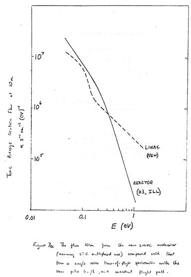
angular divergence is only of order 0.30. Figure 7a shows the flux
calculated at a 10 m sample position for the new Harwell LINAC (assuming a
factor 10 increase in useful flux over the old LINAC) compared with measured
fluxes from the H3 hot source hole at the ILL. It is seen that the new
LINAC gains over the ILL for energies over 0.3 eV, (0.5Ǻ). It remains
within a factor of two of the ILL over the whole range appropriate to the
hot source.
24. We next review the direct comparison made between the elastic
diffractometer D4 on the hot source and the Total Scattering Spectrometer
on the old Harwell LINAC by Clarke LIWP/73/P.9. The two spectrometers
have very different configurations but were both designed to measure
elastic structure factors at high scattering vectors. D4 employed a zinc
monochromator and scanned against scattering angle at constant wavelength.
The TSS employed a white neutron beam and scanned against wavelength at a
constant scattering angle of 1500. Resolution was comparable at high Q
values. The mean counting rates recorded for the same 6 mm diameter
vanadium rod are as follows.
Figure 8 shows the measurements on liquid nitrogen performed in the same
manner. It is clear from the figure and the recorded count rates that
for Q values of order 15Ǻ-1 even the present Harwell LINAC has comaprable
performance to the ILL hot source. For Q values of order 30Ǻ-1 the
advantage is overwhelmingly on the side of the LINAC. The reasons for
this exceptionally good performance compared with our rotor comparison
of the previous paragraph lie in the poor reflectivity (-10%) of all
monochromator crystals at these wavelengths and even more in the back
scattering geometry which allows very relaxed angular collimations in both
incident and scattered beams. Exceptionally good performance has also been
noted in back scattering powder patterns. There is no doubt that the
ability to exploit the back scattering configuration is a major advantage
of pulsed sources.
The Condensed Matter Target Cell
25. Figure 9 shows the planned general arrangement of the Condensed
Matter Target Cell. The layout shown had been designed and approved by
a small "Target Cell Discussion Group" convened by D. H. C. Harris
representative of the principle SRC and Harwell LINAC users.
26. The cell is constructed from poured concrete of at least 3m thickness.
This was judged from published calculations and overseas experience to be
the minimum allowable. It is expected'that this wall thickness will
reduce radiation levels within the experimental hall to permissible
working levels. With a target room width of order 3 m this gives maximum
flight paths of order 4.5 m. The target cell would be constructed largely
of conventional poured concrete. However a band of concrete loaded with
iron shot would be included in the plane of the beam tubes to compensate
for the shielding loss caused by the beam tubes themselves. This would be
+/- 0.25 m. high near the outside of the cell (two fast neutron scattering
lengths), 1 m high up to one metre from the inner wall of the cell, and
2 m high in the region of the short flight path holes.
27. The target would be of natural uranium, water cooled, and built to
handle 100 KW of beam power. Targets handling up to 60 KW are in routine
use on ORELA but detailed design of a 100 KW target was still in progress.
It will probably be necessary to install a tungsten target in the first
instance to test the target window and cooling system. This would give
around half the flux of a uranium target but would minimise the dangers
from any target melt-down. The target will be remotely lowered into a
service duct and moved out of the cell to the target service building when
necessary.
28. Allowance for the provision of a booster project further down the
electron beam line has dictated the general arrangement of the moderators
and flight tubes. A new 6 m wide concrete tunnel could be constructed on
the flat face on the left of the cell in figure 9, linking the new booster
cell with the existing electron beam line. When the booster was in
operation the existing target would be lowered allowing the electron beam
to be transmitted to the booster cell. Hole 7 in figure 9 is therefore of
large size and will also provide access to the target room for bulky
components. This arrangement will allow booster development to continue
in parallel with use of the existing cell experimental programme, with
relatively rapid change of electron beam path.
29. The beam tube layout has the general form of two horizontal fans of
tubes from two moderators on either side of the target. It is envisaged
that one of these moderators would be cooled to liquid nitrogen temperatures
allowing epithermal neutron performance to extend through the 1 Ǻ wavelength
region. The other would be a conventional thermal moderator
appropriate to higher energy neutron experiments. Both these moderators
would be in line with the beam hole as sketched in figure 10. This
arrangement gives the largest thermal flux since the moderator accepts the
maximum solid angle of fast neutrons from the target. However it means that
the g and fast neutron flash from the target is transmitted down the beam
tubes giving a radiation level in the beam of order 500 R/h comparable
with that from a reactor tubes.
30. The radiation problem is reduced by employing a through moderator
offset from the target line, and it has been decided to use the space above
the target for the future installation of such a moderator (the space
below the target is required for'target services). As shown on figure 10
this is placed to intercept only a small solid angle from fast neutrons
from the target, A fast neutron reflector is therefore required to feed
fast neutrons into the moderator. To'avoid pulse broadening effects it
is then necessary to line the reflector with a "de-coupling" layer to
absorb any neutrons moderated to thermal energies in the reflector. Much
work on this type of moderator has been recently done in conncetion with
the ZING project where the high proton energies make an on-line moderator
out of the question (Carpenter and Marmer ANL-SSS-72-1, Argonne Report).
We have therefore positioned a second array of horizontal beam holes 400 mm
above the electron beam height.
31. There are 18 beam holes in the proposed layout. This number being
dictated by a requirement that holes on the same plane be spaced at around
1 m at the cell face. This is a smaller spacing than permissible on a
reactor because only a few of the instruments need be situated close to the
cell face, and because there is no problem of reactivity loss. The 18 holes
are subdivided as follows;
a) 5 standard holes on the ambiant moderators
b) 5 standard holes on the cooled moderator.
c) 1 short flight path "gallery" hole.
d) 1 large rectangular aperture leaving flexibility for experiments
requiring rotating collimators, off-set holes for crystal
monochromator or rotating crystal spectrometers, or guide tubes.
e) 5 standard holes looking at the through moderator.
32. The standard holes (a) to (e) above will be of stainless steel tube
of 200 mm smallest inside diameter with a step to a 250 mm size near the
face. These will initially all be filled with resin and lead shielding.
As each hole is brought into use, they will be fitted with internal
collimators and evacuated. Remotely controlled beam shutters located in
the target cell will also have to be fitted at this stage if permissible
reactivity levels for work on these spectrometers are to be reached during
operation of the cell. It is envisaged that the funding of these items
will be done in association with the individual spectrometers, as it is
expected that the holes will be brought into use as required over a period
of years.
33. The building to house the condensed matter cell and its associated
spectrometers is not at present decided or funded. Construction would
ideally occur after the completion of the target cell scheduled for July '77
and be completed by the end of 1977 to allow adequate time for the
installation of spectrometers before the LINAC start-up scheduled for
May '77 (see figure 11). Local design should be complete by January '76 to
meet this schedule. The hall has already been considered by the Target
Discussion Group who recommended consideration of the 14 m x 25 m building
outlined in figure 11. The detailed positioning is dictated largely by
constraints from the rest of the project. The 14 m width down the
electron beam direction is relatively narrow compared to the length to
minimise the interaction with the proposed booster. The 10m maximum flight
path allowed on ambiant moderator side is imposed by the long nuclear
physics flight path N1 and by the target service building. There are no
restrictions on the cooled moderator size where longer flight paths are
more likely to be required. The loose block hole 10 which would be suitable
for the installation of guide tubes points to the corner of the proposed
building allowing flight paths of 17 m. The Discussion Group also
recommended a 10 ton overhead crane and vehicle access for the building to
permit rapid moving of spectrometers and ad hoc shielding.
The suggested building has an area of 350 m (3200 sq. ft.) and priced
at UK Pounds 25/sq. ft. would cost UK Pounds 80K.
34. The experimental facilities proposed would put acute pressure on the
laboratory and office accommodation of the existing LINAC, building 418.
The Discussion Group advised the provision of a substantial building giving
office accommodation for about 30 people, 6 laboratories for cryogenic work*
simple preparation and counting rooms. A 2,000 sq. ft. building at UK pounds35/sq. ft.
would cost 870K.;
A Possible Choice of Instrumental Priorities
35. The appendix contains a list of possible LINAC instruments, their
present,status of development, their scientific objectives and performance,
and an approximate Installed cost. The rate at which the new LINAC beam
holes can be exploited must be severely limited by manpower and financial
resources and we give here a possible choice of instrumental priorities.
The objectives being to produce an instrumental portfolio which is most
complementary to the existing reactor portfolio, which exploits the
favourable epithermal flux available from a LINAC, and which enables us to
utilise our existing hardware and experience.
26. Data collection and display for the 1977 instruments would be from the
dedicated computers, and a simple existing hard wired time-of-flight
analyser (LABAN) for the Inelastic Rotor Spectrometer. As the number of
time-of-flight instruments installed increased it would seem desirable to
combine certain functions such as display, hard copy and data transmission
facilities. Initially it would be practicable to use one of the existing
GT40 computers for this prupose, but by 1978 this would become impracticable.
It is therefore suggested that a "hub" computer such as PDP11/45 at around
UK pounds50K should be purchased in 1979.
27. The funding programme including moderator, buildings and spectrometers
might therefore resemble at December 1974 prices;-
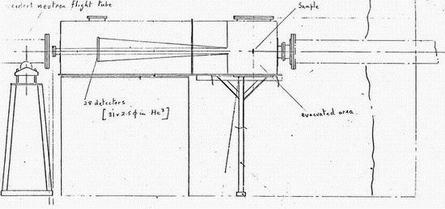
A1. The Total Scattering Spectrometer (TSS)
Status
Under construction. Expected commissioning December 1975. Planned
to transfer to the new LINAC.
Purpose
The spectrometer is designed to measure the structure factor S(Q) as a
function of Q from 0.5 to 60 Ǻ-1, Measurements can be done on liquids,
particularly molecular liquids where structure extends to large values of Q,
on amorphous solids and on crystalline solids.
Construction (see Figure A1)
The machine is constructed with a 5.5 m incident flight path and has 6
counter banks at angles of 1500, 900,
500, 350, 200 and 100. Each of the
counters are at a scattered flight path of 0.46m and are designed with curved
slits of appropriate curvature to follow the Debye Schorrer cones.
There are monitor counters before and after the specimen, allowing some
estimate to be made of the absorbtion.
The sample region diameter is 27cm allowing sufficient room for both
cryostats and furnaces. Sample size is up to 50 x 50 mm.
A 6 position sample changer is available allowing simultaneous acquisition
of sample, can, vanadium and empty cell spectra.
Data acquisition is by an on-line dedicated GT40 system. This allows
display of the data while accumulating, and immediate subtraction and
normalisation of spectra. A hard copy graph and numerical output is provided
by a printer/plotter.
Resolution
With a cooled or poisoned moderator the 1500 bank gives a resolution
DQ/Q of 0.010 independent of Q. Other banks have slightly inferior
percentage resolution of order 0.02 -> 0.05.
Intensity
The time average intensity per resolution element at the specimen is
2.104 ns-1cm-2.
Problems and Papers
Nucl. Inst. and Meths., 117 (1974), 445, Sinclair, Johnson, Dore, Clarke and Wright.
A2. The Back-Scattering Spectrometer (BSS)
Status
Operational. Planned to transfer to the new LINAC.
Purpose
The spectrometer is designed to measure the diffraction pattern in the
range of Q between 7 and 60 Ǻ-1 with 0.3% resolution. Measurements can be
done on powdered crystalline samples, when the profile fitting technique may
be used for analysis, and also on liquids or amorphous solids when better
resolution than available with the TSS is necessary.
Construction (see Figure A12)
The machine is constructed with an 11 m incident flight path and has
two counter banks at a scattering angle of 1700. Each covers the range of
angles from 1650 -> 1750 using a time focussing geometry and give a total
solid angle of .05 ster. The sample to detector distance is ~2 m. The
counter box, sample region and exist beam pipe are evacuated to eliminate
air scattering.
There is a monitor before the specimen allowing background subtraction
and absolute normalisation.
The sample region diameter is 50 cm to provide room for furnaces,
cryostats and pressure cells. Sample size is up to 50 x 25 mm.
A 5 position sample changer is available; it may be operated at ambient
temperature or at liquid nitrogen temperature.
Data acquisition is by an on-line dedicated ET44 system (subject of
final approval). This allows display of data while accumulating and
immediate subtraction and normalisation of spectra. A hard copy graph and
numerical output is provided by a printer plotter.
Resolution
With a cooled or poisoned moderator the spectrometer gives a resolution
DQ/Q of 0.003 independent of Q.
Intensity
Time average flux on specimen 700 ns-1cm-2 per resolution element.
Problems and Papers
The main problem is one of frame overlap. This will be tackled either
by an overlap filter, unscrambling the spectra or reducing the repetition frequency.
SB 72/74
A3. The Inelastic Rotor Spectrometer (IRS)
Status
Prototype in construction. Operational summer 1975 - proposal for an engineered version.
Purpose
The spectrometer is designed to measure S(Q,omega) in the energy transfer
range from 50 to 500 meV at medium Q values. Measurements can be made on
incoherently scattering molecular samples to observe optical and internal
molecular modes of excitation.
Construction (see Figure A3)
The machine is constructed with a 5 m incident flight path and ~1 mm
from the sample the beam. is chopped with a spinning rotor which is phased
to the source pulse. Scattering is observed in banks of detectors at
scattering angles of 50, 100 and 150 placed 3 m from the sample.
There are two monitor counters before and after the sample allowing
background normalisation and measurement of the incident energy.
The sample region is evacuated and allows cryostats to be used without
their normal outer containers. The sample size is 50 x 25 mm.
Data acquisition will initially be by hard-wired time-of-flight analysis.
Subsequently it would be hoped to use a small dedicated mini-computer system
which would transmit data to a larger computer for examination, preliminary analysis, etc.
Resolution
DE0/E0 = 2% when E0 = 300 meV
Intensity
Time average flux at the sample (when E0 = 300 meV) = 104 ns-1cm-2.
Problems and Papers
HNBFC/P.,2. Sinclair.
A4. The Crystal AnalyserSpectrometer (CAS)
Status
Prototype in operation on cell 2 until 1971. Proposal only.
Purpose
The spectrometer is designed mainly to measure S(Q,omega) in the region of
high energy transfer (omega) and 'low' momentum transfer Q. Measurements can be
made on molecular systems to study the internal modes. A second area of
research is the study of high frequency excitations in. magnetic crystals.
Measurements can also be made at high Q values in order to study recoil effects.
Construction (see Figure A4)
The machine is constructed with a 5 m incident flight path and energy
analysis of the scattered beam is accomplished by a curved crystal analyser
of total, flight path length ~1 m. The crystal is made up of oriented CuBe
crystals (or Be equivalent) cut to reflect (331) plane 100 meV neutrons into
a phase detector. Time focussing on the analyser allows a large solid angle
through the analyser without spoiling the incident beam resolution
determination. The geometry allows very high energy transfer to be observed
without contamination from scattering to the (662) at 400 meV,
A monitor in the input beam allows normalisation of the results for
background subtraction.
Data acquisition is based on a small mini-computer that is linked to
a larger computer for data examination and preliminary analysis.
Resolution
DE0/E0 = 0.02.
Intensity
Time average flux at the sample 24 ns-1cm-2 (per resolution element).
Problems and Papers
J. Chem. Phys. 55, 2807 (1971). Day and Sinclair.
A5. Cross-Section Spectrometer (CSS)
Status
Existed up till March 1975 on cell III. Proposed for the new LINAC.
Purpose
The facility is designed to measure removal cross-sections in the energy
range between .005 eV and 10.0 eV. Measurements can be done on scattering
samples in order to determine parameters for multiple scattering correction
and on special samples in order to derive total scattering cross-sections.
These can be used to estimate incoherent cross-sections, to derive mean
Kinetic energy values or may be needed for reactor design purposes.
Construction (see Figure A5)
The machine is constructed with a 5 m incident flight path and a
flight path for the transmitted beam of 2 m. Converging-diverging geometry
is used and gives an adjustable sample size of -10 mm diameter.
A monitor before the sample allows normalisation for background and
transmission determination.
Two sample changers each with 3 positions allow the sample to be
oscillated and filters for background determiantion to be inserted in the beam.
Data acquisition is by a small dedicated mini-computer which transmits
data to a larger computer for examination, preliminary analysis, etc.
Resolution
DE/E = 0.01 for 0.025 < E < 1.0 eV.
Intensity
The open beam intensity at the detector is ~104 per resolution element.
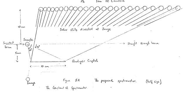
A6. Constant Q Spectrometer (CQS)
Status
Simple single counter prototype in operation. Projected for the new LINAC.
Purpose
The spectrometer is designed to measure coherent inelastic scattering
from sinle crystal samples. S(Q,omega) is observed over a wide range and the
geometry of the experiment allows constant Q, scans to be obtained in chosen
crystal directions. Measurements can be made on optical phonona, internal
modes in molecular crystals, and on magnon modes. Its absence of a crystal
monochromator gives it a relatively large incident flux at epithermal
energies.
Construction (see Figure A4)
The machine is constructed with a 5 m incident flight path and has a
large area single crystal as analyser placed close to the sample. Neutrons
reflected from the analyser are detected by a bank of 24 3He counters,
(or by a position sensitive counter) as in a MARX spectrometer. Each position
channel must be recorded as a function of time-of-flight and the constant Q
locus derived by interpolating between positional and time channels.
statistical accuracy in the constant Q scan would be optimised by appropriate
averaging over positional and time channels according to the calculated
resolution function. Thus a small dedicated computer with Fortran capability
would be highly desirable. The sample angle should be computer controlled
for ths automatic sequencing of eonstant Q scans. Sample and analyser
orientation should be remotely controllid but need not be computer controlled.
Resolution
Incident energy resolution (8m) DE/E = 0.02. (~2 meV)
Intensity
Flux incident on speciment (lamba=1Ǻ) 108 ns-1cm-2Ǻ-1.
Problems and Papers
A range of analysers with diverse d spacings is needed if constant Q
scans over a range of energies and scattering vectors is to be achieved.
C. G. Windsor, HNBFC/74/p
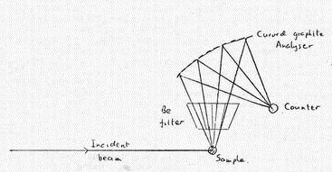
A7. Chemical Inelastic Spectrometer (CIS)
Status
Proposal only.
Purpose
The spectrometer would measure inelastic scattering from hydrogenous
compounds. The Q range of the measurements may be varied in the high
to medium range by using low or medium analyser energies.
Construction
Construction (see Figure A7)
The spectrometer is constructed with an incident flight path of 5 m and
energy analysis of the scattered beam is accomplished by a curved graphite
crystal analyser combined with a Be filter. Data acquisition is based on a
small mini-computer that is linked to a larger computer for data examination
and preliminary analysis.
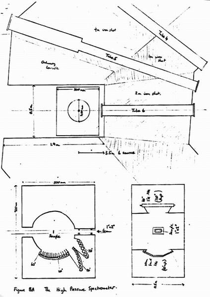
A8. High Pressure Spectrometer (HPS)
Status
Proposal only
Purpose
The spectrometer would be designed to measure the diffraction pattern
in the range of Q between 1.5 and 20 Ǻ-1 with around 5% resolution.
Measurements would be possible, on gases, liquids, glasses and crystalline
powders. We calculate a count rate of order 104 ns-1
per resolution element
allowing 1% statistics to be achieved each second from a 10% scatterer
covering the full beam. This would allow studies of the time-dependence of
reactions and phase changes. It should also be possible to study adsorbed
gases on surfaces and other minority phase problems in chemistry, and metallurgy.
Construction (see Figure A4)
The spectrometer would-be built around the "gallery" hole allowing a
3.5 m. flight path from moderator to specimen. The 1.7 m. iron shot loaded
concrete wall should permit satisfactory background levels for the
spectrometer if not for personnel. (Access would almost certainly be limited
to periods when the beam shutter is closed). The 450 moderator take-off and
the use of the thermal moderator mean that time resolutions of around 3%
would occur. Matching this to a large area counter bank giving a 4%
cotqaDqa resolution would given an overall resoltuion of DQ/Q = 5%. For the
highest intensity work it would be feasible to have several counter banks
each employing time focussing and placed along Debye-Scherrer circles.
Neutrons counted by each bank could be processed on-line to remove channels
contaiminated by the y flash or the booster peak, and sorted into bins
representing steps in 0 coiwiensurate with the resolution. Thus data from all
the counters could be presented as a single diffraction pattern when desired.
A large counter bank solid angle would be made feasible by using short
scattered flight paths between 250 and 400 mm. Using 1" 3He counters and a
30 mm diameter specimen this would give a scattered beam divergence of 5 degrees
allowing the required resoltuion to be achieved for scattering angles above
1000. Using a 10 mm diameter specimen and counters would allow the 5%
resolution requirement above 600 scattering angle.
A specimen surround of 400 mm and a head-room of 1.5 m. could be provided
giving ample-space for cryostats, furnaces or pressure rigs.
Resolution
Overall resolution requirement DQ/Q = 0.05.
Intensity
Total pulsed flux at the specimen position
(2.6/l).106
ĀĀĀn s-1 cm-2 Ǻ-1 A9.beryllium Filter Spectrometer (BFS)
Status
Preliminary measurements performed by R. Sinclair (unpublished) in 1970. Proposal only.
Purpose
The spectrometer (like its reactor analogue) would measure inelastic
vibrational scattering from hydrogenous molecular compounds. The small
scattered wavevector (k' < 1Ǻ-1) means that inelastic spectra are recorded
at relatively large values of the scattering vector Q. For 900 scattering:
Q~ k0/SUB> = sqrtE(meV)/2.07. The reason for duplicating the technique on the
LINAC stems from its higher expected count rates for energy transfers above 200 meV.
Construction (see Figure A4)
The performance of the spectrometer depends critcally on reducing the
sample/counter distance, since the time spread of the scattered neutrons
depends on the velocity spread of the slow ~5Ǻ neutrons transmitted by the
filter. The design indicated achieves this by encasing sample, filter and
beam shield within a single liquid nitrogen cooled cryostat. Large scattered
beam solid angles are then possible. It would also be possible^to employ the
Be, BeO difference technique to improve time and energy resolution.
Problems and Papers
Bajonik et al. Inelastic Scatt. of Neutrons (IAEA Vienna), 1965, 2, p.519.
Distribution-
R L0 (m) alpha0 (░) nsample(l) nres(l) - - - ns-1cm-2Ǻ ns-1cm-2 0.01 4 2░ 2.106/l 2.104 0.006 6.7 1.2░ 7.105/l 4.103 0.003 13 0.6░ 2.105/l 600 0.001 40 0.2░ 2.104/l 20 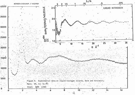
Spectrometer Wavelength range (Ǻ) Q range (Ǻ-1 Background (n-1 nres(l) TSS (Harwell) 4 - 0.4 3 - 36 140 40 D4 (ILL) 0.7 3 - 17 85 31 D4 (ILL) 0.35 3 - 33 4 2 
# Instrument Status Field Year Cost 1. Total Scattering Spectromete Exists Structure factors 1977 UK pounds10K 2. Back Scattering Spectromete Will exist Powder Diffraction 1977 UK pounds10K 3. Inelastic Rotor Spectromete Prototype exists |Molecular vibrational 1977 UK pounds100K 4. Crystal Analyser Spectromete Has existed |at low Q. Magnetic scattering 1978 UK pounds30K 5. Cross-Section Spectromete Has existed Nuclear data 1978 UK pounds20K 6. Costant Q Spectromete Prototype exists Phonons/magnons 1978 UK pounds50K 7. Chemical Inelastic Spectromete - Inelastic spectrometry (large Q) 1979 UK pounds40K 8. High Pressure Spectromete - Low resolution diffraction 1979 UK pounds50K 9. Beryllium Filter Spectromete - Inelastic large Q 1970 UK pounds60K
Year Items Total Cost ( UK poundsK) 1976 Cold moderator (20K 20 1977 Experimental Hall (80K), Spectrometers (120K) 200 1978 Laboratories (70K), Spectrometers (100K) 170 1979 Tangential Moderator (20K), Spectrometers (150K), Computer (50K) 220 1980 -> Booster construction - 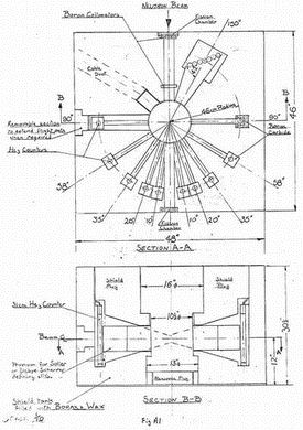
Nucl. Inst, and Meths., 114 (1974), 451, Sinclair and Wright.
Mol. Phys. 29 (1975), 561, ClarKe,.Dore and Sinclair.
Mol. Phys. 29 (1975), 1287, Page and Powles.
Mol. Phys. 26 (1973), 1325, Powles.
LIWP/73/P4
HNBFC/73/P1
Domega0/omega0 = 3% when omega = 100 meV
DQ/Q> = 5% when E0/E1 = 1.5
Neutron Thermalisation and Reactor Spectra, 1, p.389. -IAEA Vienna (1967).
G. J. Kironac et al,
Research Applications of Pulsed Nuclear Systems. IAEA Vienna, 1967, p169, PorlimKi et al.
Argonne Solid State Science Division, Research Surwn. October - September 1974
Incident angular resolution (8m) ~1░
Scattered angular resolution (2qa=90░) DE/E = 2cotqatDqa=0.04.
Flux on specimen per time resolution element D l=0.01Ǻ 104 ns-1cm-2
Flux at ths specimen per resolution element (Dl=0.05lamba) =1.35 ns-1cm-2.
Scattered flux per resolution element for 20 mm2 area specimen and 10% scatterer
2.65 ns-1
Count rate per resolution element for 1 radian2 accepted solid angle
(2.(160-60).45.50/100).1.8.104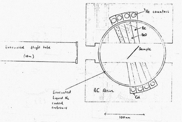
Pan. Web. Yeater Nucl. Inst. and Meths. 42, p.197 (1966).
Dr. 0. Eder, Austria
Dr. S. Amelinckx, Belgium
Professor A. R. Mackintosh, Denmark.
Professor E. F. Bertaut, France.
Dr. D. Cribier, France.
Dr. B. Jacrot, France.
Dr. W. Glaser, Germany.
Professor H. Maier Leibnitz, Germany.
Professor T. Springer, Germany.
Professor B. 0. Loopstra, Amsterdam.
Professor B. Dreyfus, France.
Professor R. Mossbauer, France.
Dr. J. White, France.
Professor A. Paoletti, Italy.
Dr. T. Riste, Norway.
Dr. R. Stedman, Sweden.
Dr. A. Furrer, Switzerland.
Dr. B. Fender, Oxford.
Dr. L. C. W. Hobbis, Rutherford Lab.
Dr. W. H. Lomer, AERE.
Professor E. W. J. Mitchell. Reading.
Dr H. B. Moller, Denmark.
Professor K. E. Larsson, Sweden.
Dr. J, Bergsma, Petten.
Professor I. Olovsson, Sweden.