
Contemporary Physics, 1998, volume 39, number 4, pages 255-282
Progress in Magnetic Confinement Fusion Research
T N Todd and C G Windsor
UKAEA-Euratom Fusion Association, Culham Science Centre,
Abingdon, OX14 3DB, UK
This article reviews the present status of research into controlled fusion using magnetic confinement of ionised gas or plasma. It concentrates on the world's leading magnetic configurations for this purpose, comprising the conventional tokamak, stellarator, reversed field pinch and spherical tokamak. These configurations are described in some detail, along with an introduction to the basics of this line of fusion research, the progress so far and the principal scientific and technical problems outstanding. The environmental implications are briefly addressed, in the context of some power generation alternatives and every-day radiation exposures.
1. The need for a fusion power source
Recent years have seen a realisation that obtaining our electricity by burning conventional fossil-based fuels is not an option that can be realistically sustained in the developed world, let alone in the developing nations. The greenhouse effect from burning such fuels appears to be changing our climate already, with hotter summers, and more extreme weather conditions that we can all appreciate. In Europe at least the mean temperature has steadily risen over the last decade. Although European emissions of carbon dioxide seem now to have stabilised, this is not true for the developing world. These would have to rise by a further factor of six to give the same emission per person as we have in Europe. The case for India, for example, was given in 1992 by Kaw[1]. At the time considered (1990) their per capita consumption of electricity was only around one quarter of the world's average, and 1/24 that of the UK. They aim, not for our level of consumption, but to attain say the present world average consumption by 2020. If their aspirations are to be satisfied by burning fossil fuels, the impact on our globe could be catastrophic.
Post-war, "atomic energy" was given as the solution to this anticipated energy shortfall. It would supply "safe, cheap power" to the whole world. That promise progressively lost its credibility, especially following the Chernobyl accident in the Ukraine in 1986. In the developed West, we could spend enough, on training and the introduction of intrinsically safe fission systems, to reduce the probability of such accidents to a socially acceptable value. But elsewhere, that option is apparently sometimes deemed too expensive. If the IAEA was to impose the highest standards on all the developing world, some countries could not afford to build or run the stations, and it would be back to coal or cold. Even without accidents, there is the perceived problem of the disposal of the high level wastes inevitably produced in the spent fission fuel.
Fusion power is quite another matter. A key difference is that the total energy stored in the plant at any one time is vastly less. It relies upon a reacting plasma which is only a very thin gas: more like a vacuum. If you can make it burn, in the sense of obtaining more energy than you have put in, you can extract its energy, but the burn cannot be sustained for any significant time without more fuel. Like in a natural gas burner, it must be continually replenished by injecting new fuel gas and extracting the spent products. In addition, radioactive decay heat power is relatively low, so there is no conceivable "meltdown" scenario, since there are also no reserves of fuel held at the high temperatures necessary for the fusion reactions. Thus there can be no Chernobyl, nor even Three Mile Island. A further difference is that the world s fusion resources are essentially unlimited. Deuterium is a widespread natural isotope, while tritium is easily manufactured during the fusion process by generation from lithium, which is fairly abundant on land, and much more so in the oceans.
2. Fusion Basics
2.1 E = mc2
The fusion of light nuclei such as the various forms of hydrogen, helium, or boron is an alternative to the fission of heavy nuclei, typified by uranium, thorium and plutonium, as a means of processing atomic nuclei to obtain power. We have all seen the tee-shirts carrying a picture of Albert Einstein and his famous equation "E = mc2", which could be said to provide the raison d'être of nuclear power. Regarding the generation of energy, or rather the transfer of energy from one form to another since energy is really conserved, the Einstein equation means that if you can create a process whereby there is less mass in total at the end than there was at the beginning, you will have released some energy. This equivalence is more meaningfully expressed as "energy (joules) = mass (kilograms) x the speed of light squared (9 x 10¹⁶ metres2/sec2)".
2.2 Chemical and nuclear energy
When chemical energy is transferred, the energy per molecular event is very small, typically of order a few eV. 1 eV is the energy gained by a particle carrying the charge of one electron, designated "e", 1.6 x 10⁻¹⁹ Coulombs, when it moves across a potential difference of one Volt, thus 1.6 x 10⁻¹⁹ Joules. The attraction of nuclear power lies in the much larger energies involved when the individual atomic nuclei suffer breaking apart (fission) or binding together (fusion), often around 1 MeV (i.e. 1.6 x 10⁻¹³ Joules). Figure 1 shows for all the elements the nuclear binding energy curve, inverted to show the excess mass energy per nucleon. Some notable features include the presence of iron (mass 56) at the minimum, the creation of two distinctive mass groups around 95 and 140 [2] as a result of typical fission events and the formation of fairly light nuclei such as helium, carbon, oxygen etc. by fusion processes.
2.3 The basic pros and cons of fusion
Unfortunately for fission, the daughter products such as caesium, strontium and the like are inevitably over-rich with neutrons and therefore highly radioactive, independently of any activation of the surrounding reactor structure. The key attraction of fusion as a power source lies in the fact that the end products are not radioactive. So as long as the structure can be made from materials which do not become strongly activated by any of the high energy particles produced by the main reactions, the possibility of a "cleaner-than-most" power generating cycle arises. However the key disadvantage, and the reason why we are only now approaching power break-even despite fusion reactions being identified as the power source of the stars in 1929 [3], is that to fuse a pair of nuclei first requires the Coulomb repulsion between their positive charges to be overcome. At very short range the strong nuclear force overcomes the Coulomb repulsion but this is only achieved by throwing the nuclei together with energies of about 100 keV. This could be achieved using a suitable combination of an accelerated beam and target. Unfortunately nature does not give us enough gain to make such an approach economically viable, with only a few collisions possible for each accelerated particle before the energy is dissipated. Thus a system featuring very many collisions of each high energy particle is needed, implying a close approach to a thermal distribution of particle energies, which leads to the need for the fuel species to be in the form of a plasma.
2.4 What is a plasma?
The word plasma comes from the Greek "a thing moulded", which is very apt since it is the ability of plasmas to be shaped by magnetic fields which makes magnetic confinement possible. (This definition of plasma is not to be confused with the alternative meaning of the liquid part of blood or milk).
A typical gas is composed of molecules; atoms tied together by chemical bonds whose strength is each around a few electron volts (eV). The binding energy of an ordinary diatomic hydrogen molecule is 2.648 eV. In chemical reactions, such as the burning of gas, these chemical bonds are broken, and replaced by bonds to other atoms. The burning of hydrogen (seen most dramatically during the Space Shuttle launches) can be represented by the equation
2H2 + O2 -> H20 + 5.922 eV. (1)
The energy released by re-arranging the chemical bonds appears as thermal motion of the water molecules created (and hence as temperature, pressure and thrust in the Space Shuttle rockets). Atoms are themselves composed of ions, the positively charged nucleus around which the negatively charged electrons move, in the famous quantised Bohr orbits. An energy of one Rydberg or 13.56 eV is sufficient to ionise a hydrogen atom, that is to separate its electron from its proton nucleus. Within the nucleus, the protons and neutrons are bound together by attractive nuclear forces which are very much stronger, so that energies of several MeV, as in gamma rays, are needed to split them apart.

Figure 1. The excess mass energy per nucleon in MeV versus elemental atomic mass. The most stable elements are seen to have intermediate masses. Fusion relies on the lightest atoms joining together, and fission on the heaviest atoms breaking apart.
In order to make a plasma, some low pressure gas must be heated or energised so that the molecules and atoms are fully ionised. The most usual method is the application of a strong static (DC) or radiofrequency (AC) electric field. In either case any electrons around are likely to be accelerated by the few volts needed to give them sufficient energy to cause further ionisation when they collide with other atoms or molecules. Simply achieving a high temperature is not an easy method for achieving full ionisation since 13.56 eV is equivalent to 157000 0C! However a weakly ionised plasma can be made in a furnace containing low pressure gas at about 2000 0C, since some particles are always moving much more energetically than the average ones.
Once the gas is fully ionised, we have a plasma and it becomes a very good conductor indeed. Less than one volt per turn of inductive voltage sends millions of amps around a large tokamak. The finite resistance causes Ohmic dissipation, maintaining the temperature of the plasma. However as its temperature rises, its resistance drops so that the rate of heating diminishes. It is for this reason that other types of heating, say microwaves similar to those familiar from our kitchens, are needed to raise the temperature of the plasma to the 10's of keV energies required for fusion.
How can the currents be induced in the plasma? The straightforward answer is to make the plasma the secondary winding of a transformer. Figure 2 shows the schematic arrangements of the windings in a tokamak. The primary winding is the inner Poloidal Field Coil or solenoid, which produces a magnetic flux variation in the centre of the machine. This flux swing induces a current in the single turn secondary formed by the plasma. In practice the iron core to route the return field is often dispensed with, in favour of more poloidal field coils.
Once the current is flowing in the plasma, it will interact strongly with any applied magnetic fields through the familiar electromagnetic forces used in any electric motor. It is this attribute which is responsible for magnetic confinement, for it is possible to design combinations of magnetic fields so that the electrons and ions which make up the plasma are confined to desired orbits, well away from any containment walls. The key component of a tokamak is the "TF" coil set providing a "Toroidal Field" around the principle axis of the plasma. This field is parallel to the direction of the main plasma current. Charged particles in strong magnetic fields tend to move in spirals directed along the magnetic field lines, forming the basis of toroidal magnetic confinement systems, in which the magnetic field lines are intended to be endless. Around the principle axis are several "PF" coils providing an adjustable "Poloidal Field". This can be used to move the plasma up or down, to squeeze its shape from a circular cross section into, for example, an elongated D shape, or to divert the outer magnetic field lines into a purpose-built target structure. The interpretation of a plasma as "a thing moulded" is seen to be accurate indeed!
Figure 3 shows the plasma in the START tokamak at Culham in its natural colours. The emissions from the centre of the plasma are in the soft X-ray wavelength range and are not visible directly, although they can be readily measured with suitable detectors. However near the cooler edge regions of the plasma, the visible radiation caused by the excitation of incompletely stripped ions graphically shows the inner and outer boundaries of the plasma. In the background the PF coils may be seen, which, together with the plasma's self-interaction, are used to mould the plasma into its distinctive shape, well away from the central column and the walls of the vessel.

Figure 3. A "true colour" picture of the START plasma. Its diameter is around 1 metre. The plasma is seen to be separated from the central solenoid (the dark column), and from the circular outer PF coils which can be seen faintly in the background.
2.5 The favoured fusion reaction
There are several fusion reactions which yield useful amounts of energy but one stands out as having a much higher cross-section than the others. This is the deuterium-tritium reaction, producing an ordinary helium nucleus and a neutron:
D + T ® He + n + 17.6 MeV (2)
where the 17.6 MeV is divided between the two products, which fly away in opposite directions with energies determined by the ratio of their masses and by the conservation of momentum, i.e. 3.5 MeV to the helium and 14.1 MeV to the neutron. Deuterium is the mass-2 isotope of hydrogen and is present in any natural water with an abundance of 0.0153 atom %. It is readily extracted by electrolysis. Tritium, however, (the mass-3 isotope of hydrogen) has a geologically short half-life of about 12.26 years and therefore does not exist in any significant quantities naturally. Some finds its way to the polar caps from the 10 kg or so continually maintained in the upper atmosphere by cosmic ray reactions. Commercially it is available from fission reactors moderated by heavy water, deuterium oxide. Neutrons in such reactors are captured by the deuterium, and form some tritium which may be extracted for use. Although this commercial source is perfectly adequate for the needs of our present fusion research programme, it could not cope with the demand if fusion power production were to become successful.
2.6 Tritium generation
Fortunately, as mentioned above, an entirely different and plentiful source exists. Close inspection of Figure 1 reveals that lithium is much less well bound than helium and in fact if made to absorb a neutron, it will split into helium and tritium. This is true for Li6, which releases about 5 MeV in doing so, but it is also true of the other common isotope, Li7, although the reaction is then endothermic, requiring about 3 MeV from the incident neutron (which is in this case re-emitted). Lithium sources on land could support the world's power production for some millennia [4], and there is more in the sea.
2.7 The temperatures required for fusion
As we have already indicated, the particle energies needed for even the D-T reaction are around 100 keV or more. Fortunately, in a thermal distribution of particles, the tail population can be relied upon to drive the reactions, so that the temperature can be perfectly adequate at a much lower characteristic energy of say 25 keV, or about 280 million degrees Celsius. Such temperatures are of course far above all material boiling points: indeed the particle energies are far above those required to strip the electrons completely from all but the heaviest elements, placing the world's fusion endeavours firmly in the realm of plasma physics. This led naturally to "magnetic confinement" as a means of achieving controlled fusion, since the plasma particles can be confined in a given volume and prevented from contact with any material structure (which would cool them down) by placing them in a magnetic field of appropriate strength and topology, as introduced in section 2.4.
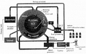
Figure 4. A generic fusion power station. The primary fuels are deuterium, from ordinary water, and lithium, present in the blanket as a lithium compound. The deuterium reacts with tritium within the plasma to make neutrons which are absorbed in the blanket and used both to raise steam and to replenish the tritium by interactions within the lithium compound. The final products are helium and electricity.
2.8 A generic fusion power plant
All the concepts have now been introduced so that a generic fusion power plant can be outlined, for example as sketched in Figure 4. Simplistically then, a plasma consisting of equal quantities of ionised deuterium and tritium (and the electrons necessary to preserve overall charge neutrality), heated to about 25 keV, is confined in some magnetic field structure and surrounded by a tritium generating blanket containing a lithium compound. The energetic helium nuclei and neutrons produced by the plasma fusion reactions heat the blanket, raising ordinary steam at the usual temperatures and pressures for conventional turbines to generate electricity.
Complexities arise even at the first steps to introduce a degree of realism into this picture. Since the required magnetic field strength is quite high (several Tesla), a fair fraction of the electricity generated would be consumed in the plant's own magnets if these were of normal conductors (say copper or aluminium) even if this was cooled to reduce the resistance, so we generally turn to superconductors instead. One then has to prevent the superconductor from being heated (or transmuted) by the neutron flux, so the blanket also has to function as a neutron shield. Also, lithium has a very low melting point and therefore is not suitable as a blanket in its pure form. Moreover it is chemically reactive, so designers opt for lithium oxide, lithium silicate or a liquid lithium-lead eutectic mixture flowing slowly in pipes of some other material (e.g. stainless steel, vanadium etc.) [5]. Since some short term activation of these other structures, and even the cooling water itself, is inevitable, no designer would allow the primary coolant loop of the blanket to provide the steam for the turbines directly (in case of leaks), so a heat exchanger to a secondary loop actually raising the steam would need to be included.

Figure 2. The tokamak configuration. The solenoid coil up the centre of the tokamak forms the primary circuit of a transformer whose single turn secondary is formed by the circular plasma. Toroidal Field coils (TF) produce a field along the line of the plasma current which serves to stabilise its path. The Poloidal Field coils enable the plasma to be shaped and positioned.
3. Progress so far
3.1 The underlying physics
Although a number of technological issues have been receiving attention as part of the development of fusion, the real essence of magnetic confinement fusion research so far has been plasma physics, with the emphasis on finding a magnetic configuration which allows the plasma to exhibit an adequately long energy confinement time. This is because the longer the energy confinement time, the less heating power has to be applied to the plasma to sustain the high temperatures for the fusion reactions. It will be evident that a system with a low overall recycling power (i.e. power consumed by the power plant itself, including any plasma heating power) is desirable for any economically viable electricity generating plant. The number of reactions per second in the plasma is given by the product of the number density of each interacting species and the rate coefficient for the reaction of interest < s v> , so-called since it is an average over the velocity distribution (denoted < > ) of the cross-section s multiplied by the particle velocity v. Thus the fusion power per unit volume generated in the plasma is given by
Pf = EfnDnT< s v> (3)
where Ef is the energy released per fusion event, nD and nT are the numerical densities of the deuterium and tritium respectively and < s v> is the rate coefficient as described just above (which has units of m3/second). For the case of D-T fusion, < s v> in the range of interest is roughly proportional to the ion temperature squared [6], so this becomes, again per unit volume;
Pf nDnTTi2. (4)
The product of the plasma energy confinement (or replacement) time t E and the heating power required to maintain the plasma density and temperature, i.e. the stored plasma energy at any instant, is given by
Ph tE = volume . kB < niTi + neTe> vol (5)
where kB is Boltzmann's constant and < > vol means the volume average. Since the electron and ion temperatures in a thermal plasma, as postulated here, will be essentially equal, while the electron and ion densities have to be very similar to preserve charge neutrality, it will be seen that the ratio of "fusion power produced" to "heating power required for temperature sustainment" can be expressed as
Pf/Ph nTtE . (6)
The left hand side here is generally denoted by Q, the power gain factor. The right hand side is called the "triple product" and has for some years been used as a measure of progress in the field, replacing the previously popular "Lawson criterion" (simply ntE) [7] which implicitly assumed a near-optimum plasma temperature rather than a temperature somewhere in the range where the á s vñ is approximately proportional to T2 (which is about 8 ® 25 keV).
3.2 Progress in plasma performance
Figure 5 shows the world's progress in magnetic confinement fusion in recent decades, as the triple product versus central ion temperature. This figure is utterly dominated by results from the so-called tokamak configuration, the subject of the next section, and shows that the expenditure so far has brought us close to Q =1. In fact there is a significant element of non-thermal fusion power generation in the best results we have obtained to date (~ 25%), so the thermal contribution to the triple product is slightly lower than plotted. Each of the three "flagship" machines (TFTR in the USA, JET in the EU and JT60U in Japan) has achieved comparable best performance in this regard. In two of these devices, plasmas of deuterium and tritium mixtures have been made (reported in more detail below), generating significant fusion power, but most of the results are inferences from discharges with only deuterium injected (for which the actual Q would be about 300 times smaller for the same triple product) [8].
The next few sections of this review will describe the leading magnetic confinement configurations, covering a little of the associated physics and the main results.
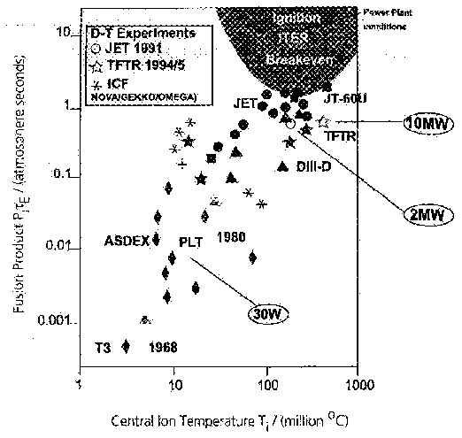
Figure 5. Progress towards the plasma conditions needed for ignition. The diagram shows the combinations of plasma temperature, density and confinement time that have been achieved so far, compared with those required for self-sustaining ignition. The closed symbols refer to inferences from conditions in D-D plasmas, while the open symbols refer to the real case of D-T plasmas. The magnetic confinement facilities involved are the Joint European Torus (JET) at Culham UK (circles), the Tokamak Fusion Test Reactor (TFTR) at Princeton USA (stars), JT-60U at Naka Japan (squares), DIIID at San Diego USA (triangles), AxiSymmetric Divertor EXperiment (ASDEX-U) at Garching Germany (diamonds) and the T3 tokamak at Moscow Russia. The open stars denote the alternative, inertial confinement, systems.
4. The Tokamak
4.1 Ontogeny and etymology
The tokamak configuration was invented in Russia and emerged as the contemporary favourite in some pivotal collaborative experiments in 1969, when a mostly British team (Peacock, Robinson, Forrest, Wilcock and Sannikov) definitively measured the plasma electron temperature by characterising the Doppler shift observed in ruby laser light from the Thomson scattering of light by the electrons in the plasma [9]. The "tokamak" is named after a Russian acronym for "toroidal chamber-magnetic". It has maintained the lead in magnetic confinement fusion research ever since these experiments and is, as will be seen, currently far ahead of the competition in this field.
4.2 The basic tokamak configuration
Figure 1 introduced the key elements of a tokamak. The most obvious feature is that it is a toroidal device wherein the dominant magnetic field (typically a few Tesla) is in the form of a solenoid. Although this geometry overcomes the disadvantage of linear systems in closing off the end loss regions, a pure toroidal field such as this (which necessarily falls off inversely with distance from the axis) is very poor at confining plasma. This is because the vertical drift of individual charged particles in the radial gradient of magnetic field is oppositely directed for particles of opposite sign of charge, resulting in a bulk charge separation between the electrons and ions, the generation of a vertical electric field and a resulting rapid additional drift, for both ions and electrons, in the outward radial direction. In the tokamak this is overcome by adding a poloidal magnetic field so that the total magnetic field consists of a set of nested toroidal helices. This has the effect of providing a short circuit for the charge separation, and results in internal plasma currents flowing down the inside and outside of the torus and up through the central region (or vice versa, depending on the magnetic field direction) known as the Pfirsch-Schluter currents [6]. The poloidal field is produced by a plasma current flowing toroidally around the machine and is typically about ten times weaker than the toroidal field. The plasma current loop thus formed would rapidly expand away from the axis due to its self-field unless prevented from doing so by image currents in a surrounding conducting shell (as in the earliest machines of this type) or by an externally applied vertical field (as in presently operating examples). This field is generally somewhat smaller than the poloidal field created by the plasma current.
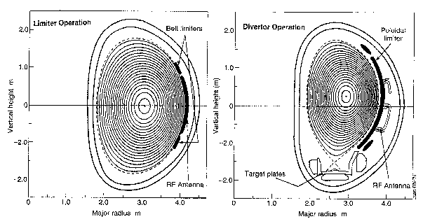
Figure 6. The JET tokamak in Limiter and Divertor operational modes. Limiter plasmas have a poloidal cross section boundary which is closed in space. This means that any impurities arising from wall interactions or fusion products recycling at the wall are ionised within the main plasma volume and contained. In single null divertor (SND) plasmas, the plasma boundary is altered by external magnetic fields to form an open surface along which ionised impurities travel to a special target area where they may be removed by large capacity pumps.
4.3 KEEPING OUT the Impurities
Finally, at about the same magnitude as the vertical field, shaping poloidal fields can be added to produce desired distortions to the plasma shape (which otherwise, in a uniform vertical field, would be close to circular). One well-studied class of shapes features one or two nulls in the poloidal field, effectively diverting any of the magnetic field lines lying outside those defining the surface with the null(s) into well-defined zones of interaction on graphite or beryllium "armour" placed within the containing vacuum vessel. This "divertor" configuration, illustrated in figure 6 for the JET tokamak in the UK, was conceived with the intention of keeping the plasma boundary region well away from the potential impurity sources of the material limiters which otherwise can easily contaminate the discharge. By installing special divertor coils at the base of the plasma, the field configuration causes a null in the poloidal magnetic field at the plasma boundary, forming an "X-point" in the contours of poloidal magnetic flux. The plasma efflux sweeps past the X-point to hit special target plates, where any impurities generated can be kept outside the main plasma and pumped away. Serendipitously, it was found in the ASDEX tokamak in 1982 that above a certain threshold in plasma heating power, the plasma, in such divertor configurations, spontaneously flipped into a mode of higher energy confinement time than usually observed, the so-called H-mode [10]. The scaling of the threshold power and the physics of the flip have been key research topics ever since, so far without any truly definitive resolution.
4.4 Field line "safety factor"
The charged particles in a tokamak plasma travel in helical paths around the torus following the magnetic field lines. In many cases the paths repeat themselves after a certain number q of circuits round the torus. For a large aspect ratio tokamak of circular cross section it is possible to match the ratio of toroidal and poloidal fields to the angle of the magnetic field line to show
(Btor/Bpol) = (2p R/2p a). q (7)
where R and a are the major and minor radii of the torus respectively. "q" is known as the safety factor, since instability of a gross kink mode (meaning one which affects the whole plasma) is theoretically predicted to occur if q falls below unity, or is arranged to be just below 2.0 (or indeed other integer values if there is a sufficiently pathological plasma current profile) [11][6]. It will be appreciated that in the real geometry, both field components vary around the poloidal circumference, even more so if the plasma is strongly shaped, such that the true field-line q can only be determined by an appropriate surface integral. A crude fit to such integrals is
q > 6Rk Btor /IA2. (8)
where A = R/a, k = b/a, the vertical elongation of the plasma cross-section (usually 2) and I is the plasma current in MA. The world's most successful tokamaks all operate with true q somewhat above 2 (or even 3), to avoid the problem of kink instability and related slower-growing instabilities.
4.5 The plasma density limit
Operation at high plasma density is generally found to be beneficial for increasing the confinement time, however raising the density raises the power lost from the electrons by ultra violet (UV) radiation resulting from excitation collisions with incompletely stripped impurity ions in the plasma. This cools the plasma at a significant rate, competing with the Ohmic heating created by the plasma current. Empirically, we observe that in devices with Ohmic heating alone, the maximum attainable electron density (averaged over the plasma cross-section) is roughly proportional to the average plasma current density and rises with reducing impurity content of the plasma. Attempts to operate beyond the limit result in radiative collapse of the edge regions of the plasma, unfavourably altering the current profile so that the plasma becomes kink unstable, much as at the low q limit described just above. The observed density limit can be qualitatively understood by noting that the rate coefficient for line emission in typical plasma impurities (such as carbon, oxygen, boron) essentially falls with increasing electron temperature (in the temperature range of interest), in much the same way that the plasma resistivity (and hence the Ohmic heating) does. Put as an inequality, we need to maintain the radiated power being smaller than the Ohmic heating power,
nenimp.< s v> rad .hn < j2h (9)
where nimp is the impurity density, hn is the (average) photon energy radiated, j is the plasma current density and h is the plasma resistivity in W m. The line radiation rate coefficient < s v> rad essentially falls with increasing electron temperature as Te-3/2 (up to about 3 keV), thus matching the behaviour of h . Both sides of this inequality rise with the impurity content of the plasma, since h is also proportional to the effective state of charge of the plasma ions, Zeff. Thus it could be argued that really, at the density limit, we are seeing the electron density squared being more or less proportional to the average current density squared, with significant variations in practice due to details of the plasma parameter profiles. Accordingly, if you want to run a tokamak at high density with little or no auxiliary heating, you will find it necessary to run it at high current density, and hence usually a large total current, as well. The addition of powerful auxiliary heating generally helps raise the density limit somewhat, depending on what it does to the various profiles and the overall impurity content [12], [6].
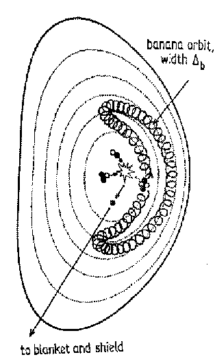
Figure 7. An illustrative sketch of a "banana orbit". An alpha particle, produced by some fusion reaction in the centre of the plasma, would make such an orbit. The particle would gyrate around the torus roughly following along the field lines, locally with a small Larmor radius, but the "guiding centre" can be projected onto the poloidal cross section to produce the banana orbit of half-width Db related to the poloidal Larmor radius.
4.6 Trapped particles
Good confinement implies favourable trapping of charged particles. In plasma physics the term "trapped" is usually reserved for particles repeatedly bouncing between magnetic field maxima, and so not escaping through the high field regions. Other examples are the Van Allen belts and the polar aurorae. In a tokamak, the variation of the toroidal field creates such a "magnetic mirror trap" and it is important to keep any particles well confined. While a mirror-trapped particle is travelling along a magnetic field line (more or less) between its mirror points, it is suffering Ñ B ("gradient of B") drift in a constant direction. This has the effect of distorting the bounce locus described by the gyrocentre of the mirrored particle, from simply an arc on the toroidal surface into a banana shape (if projected into a poloidal cross-section), as shown in figure 7, which depicts a high energy alpha particle born in a fusion reaction on a trapped particle orbit. The banana orbit represents a large-scale magnetic dipole with the opposite direction of magnetic moment to that of the small-scale Larmor orbit, thus cancelling the major radial force and recovering the equilibrium. The width of this "banana orbit" is given by
D
b (mv^ /eBq )/Ö A (10)where the term in brackets is the Larmor radius in the poloidal field, or poloidal Larmor radius, and A is the aspect ratio of the toroidal surface, A=R/a. This can be re-arranged to yield a requirement on the plasma current with respect to the (perpendicular) energy of the particle, which for a 3.5 MeV alpha particle results in
I 1.4a / (D bÖ A) (11)
where I is the plasma current within the surface of interest, in MA. Thus if one chooses a banana width of one fifth of the minor radius and an aspect ratio of 4, a plasma current of at least 3.5 MA is required to provide reasonably good alpha particle confinement, even if other fast particle loss processes are negligible.
4.7 The need for high plasma PRESSURE
Continuing with the reactor theme, let us consider the issue of achievable plasma pressure and its effect on power plant economics. We have indicated above that total D-T fusion power is roughly proportional to n2T2, which is of course equivalent to the plasma pressure squared. If we introduce the dimensionless parameter b , equal to the ratio of the plasma pressure to the supporting magnetic field pressure (B2/2m0), then we can write (with attention to the actual constants)
Pf 1.1b2B4.vol (12)
where Pf is in MW, b is a scalar (of value 0® 1), B is in Tesla and "vol" is the volume in cubic metres. Thus once we have chosen a particular power output, we can achieve it either by having a high b and small "B4.volume" or vice versa. However it costs a great deal to build a power plant with a large "B4.volume", i.e. a large magnetic field and/or plasma volume. In fact, a number of very detailed power plant studies over the years have shown that values of b 5% have to be assumed in order to achieve a cost-of-electricity (averaged over the plant lifetime) comparable to that of a typical fission-based power station.
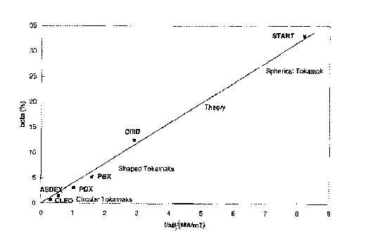
Figure 8. The experimentally achieved b values (by machine name), compared with the theoretical limit. The abscissa is I/aB, the plasma current I in MA divided by the product of the minor radius a in metres and the toroidal field B in Tesla. The theoretical limit shown is for bN=4. CLEO, PDX and ASDEX had plasmas with a circular cross section , PBX and DIIID have elongated plasmas. START is a spherical tokamak.
This has resulted in significant research effort going into "pushing the b -limits" in the last 15 years. Figure 8 summarises the results obtained over many years in this area, revealing firstly that experiment and theory are well in accord and secondly that values of b very much over 5% are readily achieved, albeit not necessarily in steady-state conditions. The abscissa shows that the critical parameter is I/aB, which inspection of the ansatz given above for q (equation 8) demonstrates can be made higher by increasing the plasma elongation, k =b/a, the ratio of the plasma vertical and horizontal radii. For several years the record value of b for a tokamak was held by the American machine DIIID using k 2.3, which allowed them to achieve a volume averaged b of 12.5%. Such experiments show that the limitation to plasma pressure in a tokamak is due to the growth of pressure-driven instabilities, essentially as predicted by theory, and that the pressure and current profile shapes are both important factors in determining the overall behaviour. A breakthrough has recently been obtained using our own device, the spherical tokamak START, which currently holds the record b of around 40%. The resulting plasmas are visually remarkable for their almost perfectly spherical plasma form. The problem of achieving such results under steady state conditions arises from our inability (at present) to control the plasma current profile with the necessary precision [13].
The question of current profile control brings us to the second most favoured toroidal plasma confinement configuration, which aims to provide all the necessary features for good plasma confinement and stability without any net toroidal current at all. It also promises an easier, or at least a more intrinsic, path to steady state operation.
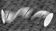
Figure 9. A schematic diagram of a stellarator showing the helical windings and the varying poloidal cross-section of magnetic flux surfaces. These devices can contain a plasma efficiently without any net toroidal current.
5. The Stellarator
The stellarator concept arose in the 1950's and represents a means of generating the full requirement of both toroidal and poloidal magnetic fields using external conductors alone [14]. This at first sounds like black magic, or at least a scheme to defeat Maxwell's equations, but it is actually perfectly tenable as an average effect. In the Japanese "Large Helical Device" (LHD) now being commissioned, the largest windings on the machine are helical, somewhat similar to the shape of the magnetic field lines of a tokamak but with a very low q (of 0.2 in this case) [15]. In this variant of a stellarator, called a torsatron or heliotron, the helical windings both carry current in the same direction. However it is easier to understand the functioning of the system if we consider that the same basic field structure could be obtained by superposing a pure toroidal field and a helical quadrupole field. Now if one follows a magnetic field line around the torus, it alternately wiggles towards and away from the helical conductors, receiving more of a poloidal field "kick" in one direction than the other, due to the strong gradients of the quadrupole field in the minor radial direction. This results in the poloidal field structure shown in figure 9, i.e. a set of toroidally nested magnetic field line surfaces of elliptical cross-section, spatially rotating to match the external helical conductors. (Since the magnetic flux within one of these field line surfaces is constant, we call them flux surfaces.) The typical q of these field lines is 0.7, much higher than that of the helical conductors and somewhat lower than the minimum values achievable at the edge of a tokamak.
5.1 The problem of magnetic islands
The two major problems of generic stellarators both stem from their fundamental requirement of strong helical magnetic fields. The first of these, which plagued most of the early stellarator efforts, is that some spatial harmonics of the main helical field can resonate with the structure of the magnetic field lines in the plasma region, with particularly strong effects at low order "rational" values of q such as 2, 3/2, 1, 1/2, 1/3 and so on. When such resonances, called magnetic islands, are made to appear within a plasma, they allow the fast parallel motion of the plasma particles to short out the radial pressure gradients which would otherwise be present, degrading the plasma confinement. In recent years, computer modelling has advanced considerably so that such effects can be reliably predicted, allowing the stellarator designers to circumvent this problem.
5.2 The problem of unconfined particle orbits
The second generic concern is that of trapped particles. If the field structure is poorly chosen, then instead of simply describing banana orbits as in the (idealised) tokamak, the mirror-trapped particles escape from the torus within one so-called "super-banana" orbit. This prompt loss is bad enough in a plasma physics research device but would be disastrous in a power plant, since a substantial fraction of the full energy alpha particles would thus be lost, generally into just a few fairly well-defined locations on the first wall. This would not only be bad for the sustainment of the fusion reactions but also for those parts of the wall so impacted, since high intensity 3.5 MeV alpha particle bombardment is difficult for any material to withstand for long. This drawback of the generic stellarator can be overcome by arranging the whole configuration to be "quasi-helical" (as distinct from just the surface, as in the classical stellarator). It then becomes possible to hide the variations in field strength caused by the toroidicity of the configuration (called the toroidal ripple) in the poloidal field ripple (called the helical ripple), leaving a one-component ripple which creates an acceptable class of banana orbits, which are not super-bananas and therefore do not generate prompt losses. The American machine HSX (Helically Symmetric eXperiment), now under construction, is of this type.
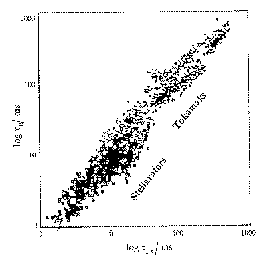
Figure 10. The Lackner-Gottardi energy confinement scaling for stellarators and for conventional tokamaks. The many overlapping symbols correspond to various facilities, with tokamaks shown as triangles and stellarators as squares. The plot shows that they both follow essentially the same general confinement scaling.
5.3 Energy confinement scaling in tokamaks and stellarators
As is clear from the above descriptions, there are many similarities between tokamaks and stellarators and in fact their behaviour in terms of particle and energy confinement is also similar. Figure 10 shows a comparison of experimentally observed energy confinement time with that predicted from a scaling law which has some basis in theory, due to Lackner and Gottardi [16]. It can be seen that the two types of machine both follow this scaling to within a small factor of error, over many orders of magnitude. We in fact have dozens of such scaling laws for global energy confinement time, nearly all of them arising simply from regression analyses of experimental data (i.e. with no physics basis). All of them show this basic similarity between tokamaks and stellarators, with varying scatter in the associated plots. Lackner-Gottardi scaling has the attraction of being based on one of the theories which predicts better confinement if the banana orbit widths can be reduced, which if true will cause advanced stellarators, as discussed below, to behave "anomalously well" compared to more conventional machines (and perhaps even tokamaks).
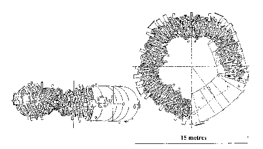
Figure 11. An example of an advanced stellarator configuration: the German machine Wendelstein-7X. Note the two layers of nested non-planar modular coils and the helically deformed high-vacuum vessel inside them. The coils are superconducting and are therefore cryogenic and enclosed within an outer vacuum vessel.
5.4 "Advanced" stellarators
A further development of recent years, led by the German stellarator group at IPP Garching, is the so-called "advanced" stellarator. This combines the two features just described with another optimisation, whereby both the deviation of the particle drift orbits from the magnetic flux surfaces and the magnitude of the pressure-driven currents parallel to the magnetic field are minimised. An example is the Wendelstein W7-X stellarator shown in figure 11, now being constructed at the Greifswald, Germany. The advanced optimisation procedure leads to a definition of the plasma surface shape and hence the magnetic field structure at this surface. Owing to degeneracies in the relationship between magnetic fields and the three-dimensional current distribution which generates them, there is an infinity of solutions for the coil shapes which can produce any one magnetic configuration. The option which is progressively gathering adherents is to make the coils of a general modular form since it allows the machine to be constructed from toroidal modules, easing assembly and maintenance problems.
6. Spherical Tokamaks
Another "alternate line" variant of the tokamak, which has its own distinctive character, is the "tight aspect ratio" tokamak, meaning a version with an aspect ratio R/a 2.5. This makes such devices resemble "cored apples" rather than the traditional "ring doughnuts", giving rise to their alternative name of spherical tokamaks. Peng and Strickler [17] were able to show theoretically that such machines open up a qualitatively different operating regime of stability and performance.
In particular these configurations were shown by Troyon et al [18] and Sykes et al [19] to have a considerable advantage in terms of the b limit discussed in section 4.8. b is economically important since the greater the ratio of the plasma pressure to the supporting magnetic field pressure, the less needs to be spent on expensive magnetic fields. Troyon showed that the beta limit could be written
bT = bN I/aB = b N5(1+k2)/2Aqcyl (13)
where b N was found to be 2.8 in his work. k is the elongation b/a of the plasma, A is the aspect ratio R/a and qcyl ~(1-1/A)qedge. Spherical tokamaks combine a large natural elongation k with the low aspect ratio A and so give a high beta limit. As the aspect ratio is reduced, the natural elongation gradually increases due to the self-interaction of the plasma loop. This is distinct from any further elongation produced by shaping coils. The advantages of divertors have been given in section 4.3, but at conventional aspect ratio they are produced by shaping and elongating the plasma using special, quite large, poloidal field coils. For spherical tokamaks, the natural elongation gives rise to a natural polar divertor which is easily changed into a poloidal divertor by small external coils [19].
The second important improvement is that geometric effects allow the ratio of the poloidal magnetic field to the toroidal magnetic field to become much larger at low aspect ratio for a given operational safety factor q [17]. This has important economic implications since it means that for a given plasma current requirement, the toroidal magnetic field strength can be greatly reduced.
A third factor, explored theoretically by Carreras et al [20] is the relative freedom of spherical tokamaks from instabilities, particularly the major instabilities described in section 8.1, which lead to "disruptions", such as the vertical displacement event. Here a small vertical movement in the position of an elongated plasma causes it to accelerate vertically up or down into the surrounding structures, in the absence of sufficiently powerful feedback circuits. This instability results from the quadrupole field used to produce the elongation and is weak or absent in a spherical tokamak where the elongation is achieved naturally.
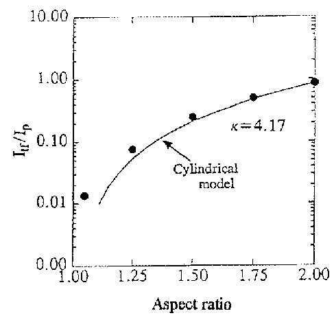
Figure 12. The required toroidal field current Itf, divided by the plasma current Ip as a function of aspect ratio R/a for theoretical reconstructions with safety factor q(a)=3 and an elongation k=4.17, after Huang et al [21].
6.1 Theoretical predictions for Spherical Tokamaks
Key factors for any fusion power plant are to be able to operate with high plasma currents with relatively low magnetic fields in order to achieve a high beta, and to be able to have continuous operation or at least long pulses. These two conditions must all be within a region of stability. More recent studies reported by Hwang et al [21], and in the 1996 Spherical Torus Workshop [22] Hender et al [22] and Lin-Liu et al [22], have now verified the possibilities by equilibrium reconstructions. Figure 12 shows the ratio of the toroidal field current to plasma current as a function of aspect ratio. There is a rapid variation with plasma currents exceeding TF currents at for example, an aspect ratio of 1.4 and elongation of 1.7. The high plasma current leads directly to high beta through the I/aB term in equation 13. Long pulses can in principal be achieved by using the "bootstrap current", considered further in section 8.5, to add to the induced plasma current. This current is generated by the plasma pressure gradient and is essentially proportional to A-1/2. Since a small current drive can be provided, for example, by RF sources, the bootstrap can provide the remainder of the total current at low aspect ratio.
6.2 Problems with spherical Tokamaks
There are several good reasons to suggest caution despite these theoretical advantages. Firstly there is the problem of constructing the central rod. As the aspect ratio is reduced, the diameter available for carrying the toroidal field (TF) current, and any solenoid to drive the current, is reduced. For a given TF current, the Ohmic heating power in the rod will rise as the diameter decreases, and the current density rises, leading to a very rapid 1/(diameter)4 variation in the temperature rise. The problem is complicated by mechanical considerations which may make a long thin structure unable to withstand the stresses and torques arising from the TF currents. Cooling the central rod would successfully reduce the Ohmic losses but could lead to quite large fractions of the output power being devoted to refrigeration. Compromises have to be made and while aspect ratios of 1.5 are readily achievable, an aspect ratio of say 1.2 would require special development. Superconducting central rods seem unlikely since they would have to be shielded from the neutron flux in any power plant, and the shield would add too much to the core diameter.
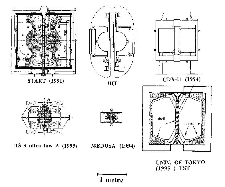
Figure 13. Schematic outlines of Spherical Tokamaks operating world-wide in 1997. START is at Culham UK, the Helicity Injection Tokamak (HIT) is at Seattle USA, CDX-U is at Princeton USA, TS-3 is at Tokyo Japan, MEDUSA at Wisconsin USA, the Tokyo Spherical Tokamak is at the University of Tokyo.
6.3 Spherical Tokamak Experiments
The Spherical Torus Experiment (STX), which was to have been constructed at Oak Ridge National Laboratory exploiting these possibilities, was never built. It was left to Sykes et al [23, 24] to build START (R 0.3 m, I 200 kA) at Culham in the UK, in 1991. This modest machine fully demonstrated the promise of the approach. As a result, START has now been given powerful auxiliary plasma heating in the form of a neutral beam (courtesy of the institute in the USA which started it all, Oak Ridge), and this has enabled it to achieve a world-wide record for the central beta of over 30%, as mentioned in section 4.8. Figure 13 shows START compared to the other presently operating spherical tokamaks. The advantages of disruption suppression have been confirmed by results at the smaller, but even tighter aspect ratio tokamak MEDUSA at Wisconsin, USA. In results reported at the Spherical Torus 96 Workshop [22] Fonck et al describe in detail the internal reconnection events which occur in spherical tokamaks. The Tokyo University TS-3 ultra low aspect ratio tokamak (ULART) has successfully demonstrated aspect ratios down to 1.1 [21].
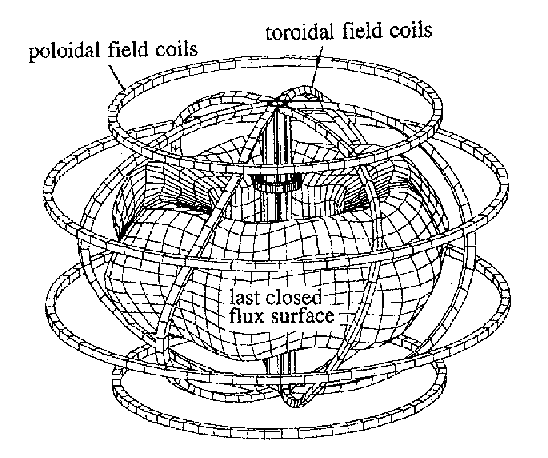
Figure 14. A perspective view of a spherical stellarator with six toroidal field coils all joined to form a common central rod. Also shown are the poloidal field coils and a representative last closed flux surface.
6.4 Spherical Stellarators
In 1996, Moroz, from Madison Wisconsin, proposed a novel ultra-low aspect ratio stellarator which he called the Spherical Stellarator [25,26]. The objective was to obtain the stellarator s advantages of steady state operation and lack of disruptions combined with the high beta and compact construction of spherical tokamaks. Figure 14 shows a design with six toroidal field coils. The inboard edges of all the coils are joined together as in a spherical tokamak, but it is seen that their outboard edges are inclined. Good magnetic surfaces were obtained for a tilt angle Df =p/N, where N is the number of toroidal field coils, typically 6 or 8. The figure shows the resulting last closed flux surface which it is seen has the usual helical form of stellarators. Such a configuration has yet to be tested, but designs suggest that it is able to achieve high beta performance together with good transport features and no need in principal for any Ohmic current transformer or auxiliary current drive system. At present the spherical stellarator, and other stellarator variants which feature large bootstrap currents as a net benefit, are in their infancy, but may be seen as an unexplored area of magnetic confinement with the potential to provide significant advantages for a future power plant.
7. Reversed Field Pinches
The "pinch effect" has a long history, being discovered experimentally in lightning conductors by Pollock and Barraclough in 1905 [27]. Once a hot plasma has been established in a cylindrical column, its current generates a magnetic field which exerts an inwards magnetic pressure on the plasma. The plasma thus contracts into a "pinch" until the magnetic pressure balances the pressure of the plasma column. In 1946 Thomson and Blackman suggested the construction of toroidal pinches, where the problems of losses at the ends of the column were removed [28]. Such pinches were demonstrated but were shown to display instabilities, such as the kink instability, where a small deflection in the plasma current channel tends to grow in amplitude. This arises from the higher magnetic field pressure on the inside curvature of a kink, compared with that on its outside.
The reversed field pinch (RFP) configuration in fact pre-dates the tokamak and stellarator, coming as it does directly from the oldest fusion research endeavours with toroidal discharge tubes, which had little or no toroidal magnetic field applied [29]. Historically the most famous of these was ZETA, which was in operation throughout the 1960's and produced inter alia two particularly important results [30]. The first of these was the observation of D-D fusion reactions created by a small population of anomalously hot ions, accelerated (like the ions in the solar corona) by strong magnetic fluctuations. The second was the production of so-called "quiescent" discharge behaviour (meaning that the magnetic fluctuations strongly decreased in amplitude) at times when the toroidal magnetic field at the edge of the plasma became reversed with respect to its direction in the central region. In the early RFP experiments, this reversal was not driven deliberately by the toroidal field winding circuit but arose naturally, as long as conservation of total toroidal flux within the plasma region could be sustained.
7.1 Relaxation and Dynamo effects
The reversed field effect was subsequently explained by Taylor as a consequence of a relaxation process trying to minimise the stored magnetic energy of the configuration [31]. The same process, generally termed the "dynamo" effect, permits the RFP configuration to be sustained for as long as the toroidal plasma current and the (reversed) toroidal field at the plasma edge can be maintained. Thus in modern RFPs, the discharge is initiated with the externally generated toroidal field in one direction, the plasma current is ramped up, paramagnetically enhancing the original toroidal field in the core region (which would, given overall flux conservation, necessarily lower it at the edge) and a combination of dynamo effect and a reversal of the current in the external toroidal field circuit produces the required toroidal field at the plasma edge. Thereafter a transformer sustains the toroidal plasma current (as in a simple tokamak) and the dynamo supports the axial toroidal field. The value of the poloidal field at the plasma edge which is consistent with a modest toroidal field reversal is invariably, as seen in Taylor's theory and in the experiments, about 1.2 times the toroidal field averaged over the plasma cross-section.
7.2 RFP problems
The fundamental problem for the RFP is that this dynamo effect is in fact mediated by low mode number instabilities, so-called tearing modes which are related to the kink modes described above but have the particular property of "tearing" the magnetic flux surfaces in order to move the flux around (thus minimising the energy of the system). They therefore generate islands (and inevitably more chaotic structures) which strongly degrade the plasma confinement, in some theoretical models allowing magnetic field lines to connect the core of the plasma to the edge region in only a few thousand toroidal transits. The result is that RFPs exhibit energy confinement times which are a very small fraction of those seen in tokamaks or stellarators of similar size, although interestingly the ion temperatures observed are generally much higher than they should be if the ions were heated by collisions with the electrons alone, due to acceleration of the ions by the magnetic field fluctuations of the dynamo. Naturally if some other means of driving the necessary plasma currents was found, these problems should be much reduced. This is one of the key aims of the MST device at Wisconsin [32], initially using high current electron guns.
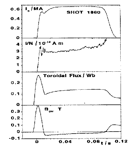
Figure 15. Typical waveforms of the Reversed Field pinch eXperiment (RFX) at Padua, Italy.
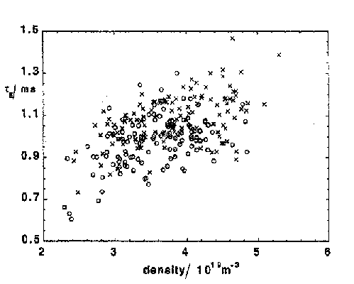
Figure16. The energy confinement time achieved in RFX, shown versus plasma density. Boronization is a wall-conditioning technique for reducing impurity emissions from surfaces facing the plasma.
7.3 RFP results
The world's largest RFP at present is RFX at Padua in Italy, which has the engineering parameters R=2.0 m, a=0.46 m, I=2 MA [33]. The operational waveforms are shown in figure 15 and the results are typified by the data given in figure 16, revealing a maximum energy confinement time of about 1.5 ms [34]. A tokamak of similar parameters would exhibit a value about 100 times larger than this, which is essentially why few countries are able to justify continued research into the RFP as a prospect for fusion.
7.4 POWER PLANT extrapolations
However, the RFP configuration features values of q which are very small, typically ~0.2 in the core, dropping through zero at the "surface" with zero toroidal field to ~-0.1 at the plasma edge. This small q introduces a "wind-up" factor into the field line geometry which allows the loop resistance to remain quite high, so that, in principle, the possibility exists to heat an RFP directly to ignition with Ohmic heating alone, whereas in a conventional tokamak or stellarator considerable investment in some form of auxiliary heating is needed. In RFPs to date, the loop resistance is generally found to be significantly higher than the plasma conductivity and field line geometry would suggest, an effect usually ascribed to the dynamo back-EMF. RFP proponents argue that if only the electron temperature can be raised to power plant values (at least 6 keV, say), the resistive dissipation which is compensated by the dynamo will be much smaller and therefore, hopefully, the dynamo will be considerably less aggressive and the confinement time will be adequate. But will they be able to reach the high temperature regime in the first place? Time may tell, but there are some interesting ideas which might help, such as using RF current drive to support the steady-state poloidal current (perhaps also to be tested in MST) so that the dynamo action is not a necessary feature of the RFP. Meanwhile, the Japanese have built another large experiment at Tsukuba, TPE-1RM20, which should help to elucidate the scaling with size and current.
8. Tokamak optimisation
Although the tokamak holds the lead in magnetic confinement fusion research, optimisation is required in a number of areas before the world can be offered an attractive alternative power source based on this line. This section considers the most important of these.
8.1 Disruptions
The most long-standing issue is the "current disruption", a sudden complete loss of plasma current and energy, seen in all tokamaks from the earliest Russian examples to the flagship machines of the present day. The more pernicious effect is the commutation of the plasma current into the surrounding vacuum vessel and/or the first wall components. The resulting stresses in the mechanical structures represent a considerable challenge to tokamak power plant designers, who have accordingly pressed the fusion physics community to come up with a reliable technique for softening or obviating the disruption.
In tokamaks with an elongation much greater than their natural elongation, the problem is aggravated by a tendency for the vertical position control system to lose control, so that the plasma moves rapidly into the top or bottom of the vessel. This rapid movement, called a Vertical Displacement Event (VDE) "scrapes off" a significant fraction of the edge or "halo" of the plasma current channel, creating additional currents in the first wall components (the so-called halo currents). We still do not have a panacea, although a number of disruption prediction and control techniques are under investigation and JET routinely demonstrates disruption softening by initiating ramp-downs of plasma current and elongation at the first signs of any pertinent MHD disturbance.
8.2 Plasma-facing components
Perhaps the most demanding technical issue is that of the power flux to the plasma-facing components. Unlike a fission reactor, which is cooled throughout the volume of the power-producing core, a fusion power plant has to have a significant proportion of its power removed at or near the surface of the plasma. Unfortunately this problem is aggravated (in present design concepts) by the adoption of a poloidal flux divertor (as mentioned in section 4.3 but see also the section on ITER, below), which focuses a significant fraction of the power output into two toroidal lines, albeit "thick" lines. This results in a demand either for some means of greatly reducing the power conducted to the divertor structures (e.g. by creating a stable surrounding radiative mantle, or some more localised zone, to convert the power into diffusely radiated photons) or for an engineering solution which can tolerate steady-state power fluxes around 10-20 MWm-2, and occasional much higher loads caused by plasma current disruptions as described above.
8.3 Helium ash
A problem now thought to be relatively minor concerns removal of the alpha particle, or helium, "ash". Just as in a coal-fired power station, if the products of burning are not removed at an appropriate rate, they dilute the fuel so that the power output declines and eventually the burn cannot sustain itself and is extinguished. This is particularly true in fusion systems where there is a critical limit to b (as discussed above) so that the density of the fuel species, deuterium and tritium, cannot be raised arbitrarily to compensate the dilution. It can be shown that in order to achieve a sustainable condition, the particle confinement time of the helium ions should be less than or equal to about eight times the total plasma energy confinement time, t E. In present experiments, this happens to be about the factor that we see, but we also observe a variation of particle confinement time with minor radius within the plasma and with the shape of the plasma profiles, particularly the density. Thus some research activity continues in this area, aimed at understanding the profile sensitivities and testing various schemes for enhancing the ash removal rate. An example is using ion cyclotron heating to pump the helium ions into such large pitch angles that they become trapped in the ripple caused by the finite number of toroidal field coils, thus leaving the plasma rapidly via the tokamak version of super-banana orbits.
8.4 Plasma impurities
Fusion plasmas will be rather intolerant of impurity ions, due to a mixture of fuel dilution and enhanced radiative cooling in the core region. The radiative losses arise from two distinct mechanisms. Firstly, collisions (i.e. close encounters producing large Coulomb forces) of the plasma electrons occur with the highly charged impurity ions, resulting in greater "bremsstrahlung" (i.e. braking radiation) than would arise with singly charged hydrogenic ions. Secondly, electron impacts excite the residual electron shells of any impurities of high atomic number, creating X-ray line radiation. Significant endeavour therefore goes into finding methods of controlling the impurity influx into the main plasma, in most cases using the screening effect created by a poloidal divertor (as discussed in Section 4.3).
8.5 Non-inductive current drive
The concept of a self-driven or "bootstrap" current, which drives from a combination of plasma pressure gradients and banana orbits, is very important for non-inductive current drive in tokamaks. If the operating parameters are appropriately chosen, it becomes possible to generate well over half the total plasma current in this way, leaving only a small fraction to be supported by other means. This opens the door to the possibility of a steady-state tokamak, if the remaining current can be driven using only a small proportion of the electricity generated, and if the total current profile can be maintained stable to all instabilities of concern. The most widely proven current drive schemes are those of near-tangential neutral beam injection and lower hybrid waves. When a beam of neutral hydrogen is injected into a tokamak, most of the neutrals are ionised by collisions in the plasma (if the density is high enough). The resulting fast ions circulate in the torus, stacking up a positive ion current. This would be quite large but is to a significant extent cancelled by an electron current arising as a result of the circulating fast ions dragging on the plasma electrons. Even so, current drive "efficiency" values of ~0.3x10²⁰ AW-1m-2 are readily achieved in today's machines [35]. Similar values are obtained with lower hybrid wave current drive, wherein a carefully phased array of waveguides launches a "slow wave" (meaning one travelling at well below the speed of light) around the torus. That part of the electron distribution function with a range of velocities just below the wave speed is then entrained in the wave (in the same way that surfers moving in the same direction as an ocean wave are gathered up by it), thus pushing extra electrons around the tokamak in a particular direction, i.e. driving a current. The theory and experimental scaling of these and other current drive techniques continues to attract a great deal of attention.
9. World distribution of toroidal confinement fusion research
It can be seen from the sections above that while much progress has been made in this avenue of fusion research, there remain challenges in both physics and engineering before an economically acceptable power plant could be produced (although proponents will be quick to point out that the definition of "economically acceptable" might change dramatically in favour of fusion if the environmental impact of most competing technologies was to become properly costed!).
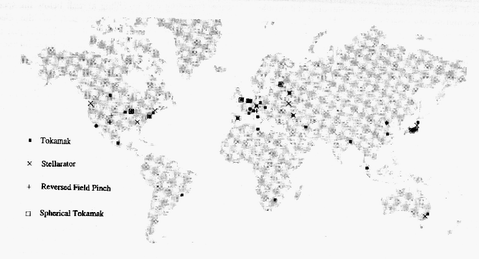
Figure 17. The world distribution of fusion research using Tokamaks, Stellarators, Reversed Field Pinches and Spherical Tokamaks.
9.1 The world scene
A surprisingly large number of countries, by no means all found in the "developed" world, are actively participating in fusion research, mostly concentrating on the toroidal magnetic confinement lines which are the subject of this article. The world map in figure 17 shows those research centres with presently or recently operating tokamaks, stellarators, RFPs and spherical tokamaks [36]. It can be seen that there are some 3 dozen tokamaks, about a dozen stellarators and slightly less RFPs operating at present. There are 7 operating spherical tokamaks, but another 5 are under construction, so representing the fastest growing sector. Inertial confinement fusion is a big field but not the subject of our review. To these popular approaches could be added magnetic mirrors, toroidal magnetic cusps, muon-catalysed (cold) fusion and perhaps even electrolytic cell or "test-tube" fusion.
At the time of writing (1998), plasma budgets in the USA have waned somewhat under general government expenditure cut-backs, and government research activity in the Former Soviet Union is somewhat depressed (while attention is focused on more pressing social issues). Meanwhile, European and Japanese fusion research seems relatively stable, Brazilian, Indian and Chinese commitment seems to be increasing, and some new players are entering the scene, most notably Korea, which seems set to build a $200M superconducting tokamak in the next few years. It therefore seems likely that the overall annual world expenditure on magnetic confinement fusion will remain at around $1000M for a few years at least, always depending on the priorities that society (and hence governments) place upon improved methods of centralised power generation and concomitant high-tech industrial development etc.
9.2 The UK programme
In the UK, our fusion effort is directed at tokamak development, in two distinct lines. The first of these relates to the international project ITER (see below) and accordingly concerns conventional aspect ratio, single null divertor, modestly elongated plasmas, as created in the Compass-D machine (R=0.56 m, I 300 kA). The Compass-D programme comprises MHD studies, such as resonant error field effects, control of disruptive instabilities, b limit studies etc. and also various aspects of the H-mode (high confinement mode). Here we have a literally pivotal role as the world's smallest device able to achieve the H-mode in a divertor configuration, since our data on power threshold, Edge Localised Mode (ELM) behaviour and so on is at one extreme of the relevant scaling law databases. The UKAEA, with its long fission reactor experience, has for a long time also played a major role in the detailed design of fusion power plants, together with detailed estimates of their performance, safety, cost, and waste disposal problems. The UK additionally continues to make a major contribution to theoretical research in fusion, in particular the key fusion power plant problems of the role of alpha particles in the energy balance, and the energy transport in the plasma edge region.
9.3 Tight Aspect Ratio systems
The second line in the UK is that of "tight aspect ratio" tokamaks described in section 5. Besides the existing spherical tokamak START, we have been given approval from the UK government and from our other funding agency, Euratom, to construct a significantly larger version called the Mega-Amp Spherical Tokamak, or MAST. Figure 18 depicts cross-sections of the two machines to the same scale, together with the design for the Component Test Facility described in the next section. First operation of the new machine is expected late in 1998. MAST is intended to demonstrate the confinement scaling of this type of plasma, in addition to non-inductive current drive, continued resilience to disruptions, very high b values, high power divertor operation and, hopefully, H-mode and ELM behaviour in this extreme geometry.
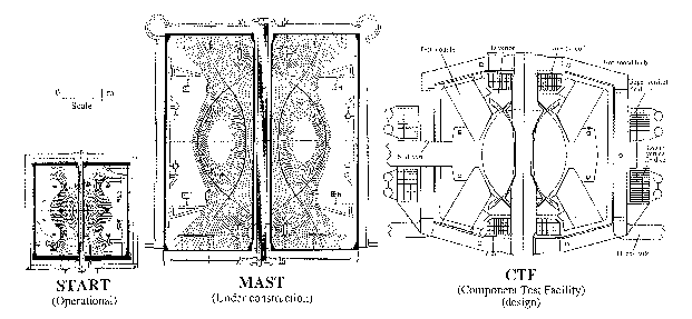
Figure 18. The UK programme in spherical tokamaks. The presently running tokamak START is compared with MAST (now being constructed), and with the Culham design study for a Component Test Facility. Note the common scale.
9.4 Tight Aspect Ratio Power Plants
The strategy of this approach is to explore the possibility of creating a power plant design which would be much more compact than the conventional aspect ratio tokamak versions, relying heavily upon the demonstrated very high b of the spherical tokamaks. The key issue here is the centre column design, which in conventional concepts comprises heavily shielded superconducting toroidal field coils and an Ohmic heating solenoid. However in the tight aspect ratio approach, this would result in a very large device with too large a power output for any immediate utility consideration. Instead, the concept is fundamentally based upon the use of a completely unshielded "single turn" central column made from ordinary copper (and forming the common path of a multi-limb toroidal field coil set), routinely removed (and recycled) whenever the neutron-induced nuclear transmutations had raised the resistivity to unacceptable values. Thus although there are no superconductors or insulators in the core to suffer any radiation-induced degradation, the problems become (i) can the power "wasted" in supporting the toroidal field be kept adequately low to satisfy the overall economics and (ii) can the plasma current be created and sustained without any central solenoid? Both should be tractable with improved physics, the first by operating at high elongation and low q to reduce the required toroidal field and the second by exploiting the natural bootstrap current and finding, if necessary, efficient and perhaps novel current drive schemes.
At the present the UKAEA are pursuing the design of a "Component Test Facility" (CTF) which was shown in figure 18 and represents the intermediate step of a powerful fusion neutron source for material tests, including whole first wall and blanket components, under a realistically severe 14 MeV neutron flux.
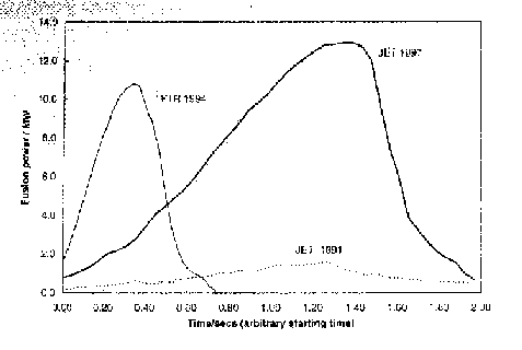
Figure 19. The variation of fusion power during pulses in the D-T experiments of the JET Preliminary Tritium Experiment in November 1991 (shot 26148), TFTR May 1994 [38], and the JET DTE1 campaign in September 1997 (shot 42676).
9.5 The Joint European Torus: JET
It will be apparent that in order to achieve significant control fusion power at the more modest b values of conventional tokamaks, you need a rather large machine, or at least one with a large magnetic field over a large volume or "B4.vol". The world's record-setting magnetic confinement devices are of this class: JET in Europe, TFTR in the USA and JT60-U in Japan. Each of these has achieved triple-products in the range where Q approaching 1.0 would be produced if the plasmas had been reasonably pure DT (as was shown in figure 5), but only JET and TFTR have performed DT experiments, since JT60U was never intended to run with tritium. In November 1991, JET ran a "Preliminary Tritium Experiment" of a few shots, producing about 1.7 MW of fusion power for approximately two seconds in a plasma with just over 14 MW of total non-fusion power input [37]. These experiments were terminated by disruptions associated with a build up of impurities within the plasma. Since then new divertor systems have been constructed whose primary function is to use large cryopumps to remove impurities in special exhaust regions well away from the main plasma.
During the summer of 1997 JET ran its DTE1 compaign in which a number of experiments were performed within a neutron "budget" of 2x10²⁰ specified to limit activation of the assembly. A shot giving a maximum power of 17 MW with 10 MW sustained over seconds was achieved as shown in figure 19. The data is undergoing analysis and it is expected to provide insights on the effects of alpha particle heating and isotope scaling of the H-mode threshold and confinement time. Another high priority was to reproduce the intended conditions in the ITER reactor, discussed below, of long pulse ELMy H-mode plasmas. These experiments are now complete and their analysis is continuing.
9.6 TFTR
For some years the JET preliminary tritium experiment stood as the record for controlled fusion power but then TFTR began its extended campaign of DT experiments and quickly surpassed JET (which had returned to a programme of deuterium operation), achieving over 10 MW of fusion power from about 35 MW of plasma input power [38], as shown figure 19. The principle parameters were R=2.48 m, a=0.8 m, I=2.5 MA, B=5.1 T, plasma electron density 9.1019 m-3. In these experiments, as always intended for TFTR, a significant fraction of the fusion power production originates from non-thermal ion collisions, mostly the ionised neutral beam particles interacting with the plasma ions but also interacting with other beam ions circulating at near their injection energy. The plasma in these experiments was highly non-thermal, with average central temperatures of around 36 keV for the ions and 10 keV for the electrons. The TFTR programme of DT operation continued for many months but ended in the April 1997. It is clear that TFTR s record for controlled fusion power production has been overtaken by JET but one can already ask "What next?", which subject occupies much of the remainder of this article.
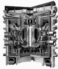
Figure 20. The Detailed Design of ITER. Note the large scale of the project shown by the men to the lower right of the figure.
10. Next Steps
10.1 Tokamaks: ITER
Several times above we have mentioned ITER, the "next step" in advancing the performance of magnetic confinement fusion systems [39]. It is designed as a large tokamak, intended to be a low risk machine in terms of ignition capability as well as, of course, all safety and environmental matters. The formal aims of ITER are to understand and control the approach to ignition and burn, and to control burn products (helium ash). The Conceptual Design Activity was completed in 1990 by a multi-national team drawn from the supporting partners of Europe, the USA, Japan and what was then the USSR. This led on to the Engineering Design Activity (EDA), which will be completed in 1998, with Russia replacing the USSR. Figure 20 depicts the version known as the Detailed Design, generated in early 1997. One of the more obvious features in this figure is the large volume (and special poloidal field coil distribution) allocated to effect the downward-pointing single null divertor. This has been included to provide screening from the main plasma of any impurity ions emanating from the areas of plasma interaction with the plasma-facing components, to guide the efflux of helium "ash" into the pumps as well as to enable the H-mode of energy confinement. The main parameters of ITER are given below [4].
|
Major radius (m) |
8.14 |
|
Minor radius (m) |
2.8 |
|
Plasma volume (m3) |
2000 |
|
Plasma current (MA) |
21 |
|
Pulse length (s) |
1000 |
|
Toroidal field (T) |
5.7 |
|
Additional Heating (MW) |
100 |
|
Anticipated confinement time(s) |
6.1 |
|
Fusion product nitrte (m-3 KeV) |
5.1021 |
|
Average wall loading (MW/m2) |
1 |
Consistent with the likely requirements of the first "DEMO" electricity-generating fusion power plant, ITER is designed to employ superconducting magnetic field coils throughout. The design also features materials for the vacuum vessel etc. which are selected from the list of those which engender a high degree of confidence when used in nuclear fission systems, in order to minimise licensing delays. Thus it is not intended to demonstrate the use of special low-activation steels etc., which will be necessary to realise the full potential of fusion as a "cleaner-than-most" power source, but which will take a decade or so of prolonged trials to prove as entirely suitable for the DT fusion applications in mind.
Cost assessments undertaken for the ITER Interim Design by each of the four partners were found to be unexpectedly close to each other, considering the complexity of the machine and all its ancillaries, buildings etc. Within about 10%, each partner determined the cost to be around $6000M at 1997 values, (around the cost of a nuclear aircraft carrier) which would be shared by the partners (albeit unevenly) and spread over the construction and commissioning period of about ten years. One could argue that, for everyone in the world, about ten cents a year over ten years would cover the construction of this machine, which of course is aimed at finding a way to meet a good part of the world's future power demand while avoiding the specific problems of fossil fuels, fission and the less environmentally friendly of the various renewables. It remains to be seen whether or not the ITER project will continue beyond the EDA stage, of course, with any successful continuation depending upon the outcome of considerations both within and external to the fusion community. It is a difficult decision, because while the optimum technical solution might well have moved on during all the years of design, the prize of demonstrating a controlled fusion power device is potentially too valuable to abandon. Presently it seems likely that the EDA will be followed by a three year detailed interim design stage specific to several likely sites, while governments decide on the issues involved.
10.2 New Stellarators: LHD and W7X
In the field of stellarators, the largest machines with approval are LHD in Japan and W7X in Germany, both mentioned above. These two machines have rather similar basic parameters (R=3.9 m and 5.5 m respectively, a 0.54 m, B=3 T, both superconducting throughout) but very different design philosophies. LHD is in an advanced state of construction and should be on line in 1998, while W7X received governmental and Euratom approval in 1995 and might be producing first plasma around 2004. Neither of them is intended to operate in DT and the predicted maximum energy confinement time in both is 0.2 s, a substantial improvement on today's best stellarator results (t E 0.05 s) but still a fair way behind today's big tokamaks (t E 1.0 s).
10.3 New Spherical Tokamaks
Besides MAST in the UK there are a number of new spherical tokamaks being constructed around the world. NSTX in Princeton USA will be the largest of these with a major radius R=0.85 m and a minor radius a=0.68 m (A=1.25) and expects its first plasmas in 1999. At Madison USA, the Medusa tokamak will be replaced by Pegasus, having R=0.42 m, a=0.37 m and the objective of reaching aspect ratios A 1.1. In St Petersburg, Russia, the GLOBUS-M tokamak is under construction and will have R=0.36 m and a=0.24 m (A=1.5). At the University of Tokyo, the TS-4 tokamak, R=0.55 m, A=1.05-1.5, will allow the opportunity to study merging plasmas. At Sao Paolo, Brazil, the ETE tokamak will have R=0.3 m, a=0.2 m (A=1.5).
10.4. Technical problems
There are many scientists in the magnetic confinement fusion research field who would claim that we know enough about energy and particle confinement scaling to be able to design a fusion device that would ignite and burn (for a while, at least) using the existing technology of superconductors, coil support structures, vacuum vessels and so on. Indeed, this is really a tenet of the ITER project. We listed above (in section 8) some of the more important areas of physics uncertainty but there are also certainly some areas where support technologies require significant improvement if reliability of operation and minimised environmental impact are to be optimised as well. Another whole review article might be justified to cover all the pertinent activity properly but here we will only present what we (as fusion experimental physicists) perceive to be the three leading concerns.
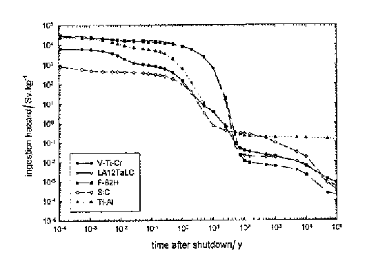
Figure 21. The ingestion dose as a function of time after the shutdown of a fusion reactor, for five candidate blanket materials. The hazard assumes that all the radioactivity ingested is retained by the body. Note the sharp drop to a relatively low level after around 50 years.
10.5 High heat flux components
Our first choice for a leading technological concern comes up almost every time a design for a large machine is discussed, particularly if it is to be a long-pulse device. It is the need for a material, or a layered combination of materials, which can provide a very high heat flux capability, as mentioned above in section 8 on outstanding tokamak problems. If the physicists cannot effect a cure by the various means outlined there, then the requirement is (ideally) for an extended surface which can tolerate a continuous power flux in the region of 20 MW/m2, exhibit very low physical and chemical sputtering of impurity ions into the plasma (lower still if the sputtered ions are of high atomic number) and survive the occasional disruption. Examples which come close to this ideal are beryllium-plated copper or carbon-fibre reinforced graphite bonded to an alloy of intermediate expansion coefficient such as titanium-zirconium-molybdenum, brazed to stainless steel. However, neither the copper nor the (conventional) stainless steel are ideal from a neutron activation point of view, while some otherwise quite desirable refractory metals (e.g. tungsten) have similar problems.
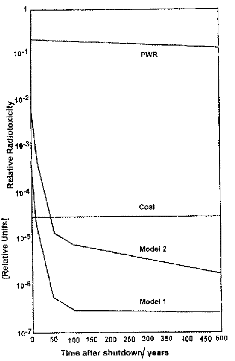
Figure 22. The relative radiotoxicity as a function of time for the waste products of various types of electricity power station: a conventional fission Pressurised Water Reactor, a coal-fired station, and two model designs of fusion power stations. Model 1 uses low activation steels, whilst model 2 assumes the use of low activation vanadium alloys.
10.6 Low Activation Materials
Such considerations lead to the second of our perceived technology development needs, which is the general issue of the need for low activation materials for all the radiation-exposed components of a future power plant. If you survey the periodic table and ask what the behaviour of each element is, when subjected to large neutron and gamma ray fluxes (both with energy spectra up to about 14 MeV), many elements either do not become activated or decay very quickly, with half-lives measured in weeks or months, rather than centuries or millennia! An important exception is nickel, which is a common component of high strength stainless steels like SS316. The most likely alternatives which are being investigated at present are a vanadium-titanium-chromium (V-Ti-Cr) alloy, the low activation ferritic-martensitic steels (F-82H and LA12TaLC), a titanium-aluminium intermetallic (TiAl) and silicon carbide composites (SiC/SiC) [40]. Figure 21 shows a calculation for the mid-blanket position of a fusion power station, indicating how these materials compare in ingestion hazard per kilogram over periods after shutdown ranging up to a few centuries.
Engineers have built up very substantial databases of the behaviour of traditional alloys such as stainless steels, in all kinds of conventional structures, with or without hostile chemical environments and nuclear fission radiation fields. They have had no real need to develop a range of specially purified or metallurgically equivalent steels which are much better in terms of resisting activation, since fission systems inescapably produce substantial quantities of long-lived, highly radio-active daughter products which have to be dealt with anyway. But for fusion the issue is much more important: if low activation materials (LAM) are not developed, a major advantage of fusion is lost. This can be demonstrated by comparing the ingestion hazards of a fusion power plant at the end of its useful life, when built with a conventional or LAM design, as is shown in figure 22 (which includes a fission system and a coal-fired system for reference) [40]. It can be seen that if the LAM programme is successful, fusion would offer the "quite green" promise of less radioactive hazard than coal within a few decades of power plant shut-down. Some of the techniques used to try to achieve suitable low activation materials include high purification to remove unnecessary impurities in alloys (such as cobalt), metallurgically equivalent replacements for alloy constituents and the development of high-performance composite materials featuring the favoured elements.
10.7 14 MeV neutron source
Last in our list of important technology requirements is a large volume 14 MeV neutron source to support the materials and component development activities required for post-ITER power plants. This is because the fast neutrons created by the DT reaction can produce damaging effects not possible at lower neutron energies. In a fast neutron fission reactor, the energy spectrum peaks at around only 1 MeV and then falls off nearly exponentially with only a fraction of a percent of the neutrons having energies above 10 MeV. In any case the sample volume available is not very large. Thus it is widely recognised that a purpose-built fusion neutron source, ideally with sample volumes ranging up to about one cubic metre, would be of significant benefit to the testing and development programme in support of fusion. There are various ways that this could be achieved. One of the candidates would be a so-called magnetic mirror machine with a highly non-thermal ion population supported by high power neutral beam injection. Another possibility attracting increasing interest might be a tight aspect ratio tokamak of modest size, also driven by neutral beams, mentioned earlier as the Component Test Facility in section 9.4 and sketched in figure 18.
11. The case for fusion: can anything radioactive be "adequately green"?
If fusion is to be widely accepted as an attractive power source for the future, then not only do the various problems in physics and engineering have to be solved, but also a sufficiently wide acceptance of the relative risks of this type of power plant has to be developed. The factual basis is quite clear: the report of the Safety and Environmental Assessment of Fusion Power [41] showed that, with the use of low activation materials, the worst possible fusion accident would not require evacuation, and that the activated material from fusion would decay rapidly and not be a burden on future generations. The improvement over nuclear fission is about a factor of 104, both for the severity of accidents and for the burden of waste management. Is this "adequately green" for social acceptance?
11.1 Perceived risk
The fascinating way in which all we humans perceive the relative risks of the things we do, or allow ourselves to be exposed to, would warrant yet another whole article, preferably by an appropriate expert and not just a physicist and fusion proponent like either of us! One of us was terrified of air travel on the first few trips I had to undertake but now I am completely blasé about it, just feeling slightly annoyed when the vibration of take-off or landing jars my writing. I know academically that neither of these responses is correct, that I should pay attention to the safety lecture on every flight etc. and have some degree of readiness for a perhaps marginally survivable disaster at take-off or landing, but at first it was all too strange, and now it is all too familiar. I see the same pattern all around me every day, be it people smoking, crossing the road, walking alone at night, undertaking hazardous sporting activities or whatever. It is therefore not at all surprising that for the majority of folk, the dangers of small amounts of radiation are either perceived as staggeringly high or, for some no doubt, inconsequential. Where does the truth lie? Somewhere in-between, of course, and society has to judge its priorities. But maybe some "background" will help the readers form their views.
11.2 Every-day radiation sources
When we were researching the radioactive content of various everyday substances for the talks which gave rise to this article, we came across a number of interesting things which help us to put radiation exposures in perspective. The first of these was that most of the radioactivity in the food we eat comes from the potassium-40 which is prevalent in much of it. Thus a book on nutrition allows us to estimate the specific activity of various common foods shown in the table below.
|
Substance |
Brazil nuts |
Bran flakes |
Tea |
Molasses |
Coffee |
|
|
Radioactivity (Bcq/kg) |
460 |
600 |
640 |
900 |
1000 |
|
Oddly, many of the "worst" examples are usually considered health foods! Fortunately, before we could start to worry about this, we found that the body self-regulates the proportion of potassium it carries to around 70 Bcq/kg and so it doesn't really matter how many bowls of fruit, nuts and bran flakes we eat, give or take a "confinement time" in the body. Potassium-40 emits beta particles of around 1 MeV, incapable of penetrating typical cardboard packaging, so we have no worries about browsing in a coffee shop either. While some radioactive materials are not recognised by the body at all, and are hence fairly quickly got rid of, the ones to worry most about include things like the fission products strontium-90 (confused by mammalian biochemistry with calcium and thus deposited in bones) and radioactive isotopes of basic body-building blocks, like iodine-119 .
11.3 "Background"
In the UK, as in most other parts of the world, the average background dose is about 2.2 mSv (milli-Sieverts) per year. Although some years ago the statisticians were divided on whether or not very low levels of exposure could be accommodated harmlessly by the body, the safety criteria have always quite rightly been set by the more pessimistic assumption of linear scaling of risk down from more reliable high dose statistics. (Recent evidence supports theory in predicting a two-level risk coefficient, with a factor two times lower applicable at low dose rates (when damage sites are no more than one per cell) [42]. From such assessments, it can be argued that while every year we each have about a 1-in-400 chance of contracting cancer from any and all sources, the extra risk if we expose ourselves to an extra 1mSv raises this to 1-in-399.96 in the relevant year, i.e. an almost imperceptible change. Here are six easy ways to give yourself this one extra milli-Sievert:
From this it can be seen that there must be a very large number of people in the world who do not think of themselves as radiation workers, yet who are exposed to annual doses equal to a good fraction of the legal limit for such workers, usually around 50 mSv per year (although about one fifteenth of this is the preferred target). Perhaps not surprisingly then, the health of the UK radiation workers in British Nuclear Fuels, Ministry of Defence, Nuclear Electric and the UK Atomic Energy Authority which has been carefully monitored as a function of their lifetime radiation dose, reveals no significant trend [43].
11.4 A personal interpretation
Meanwhile although prudence has its part, we personally feel that there is little point in worrying about a few milli-Sieverts per year more or less (since this would be within the variation of background from one county to another, or between occupations and so on), and we know that the lethal all-at-once dose is around 5 Sieverts, so the acceptable range is fairly well bracketed. We each just have to estimate what tiny fraction of those hypothetical reactors we (and our long-term descendants, in the case of fission) are going to eat each year, via all possible pathways of course, to help us arrive at a rational judgement on the acceptability of such risks.
12. Conclusions
Fusion offers a possible technique for the centralised generation of electrical power, drawing for its fuel on light elements which exist in abundance in the earth's crust and in the oceans. While the realisation of this power source for electrical generation is certainly far more difficult than is the case for many other power production systems, we believe that on the basis of present understanding and progress, we can expect to see its exploitation in the not-too-distant future.
We have discussed above the intrinsic advantages of fusion over some widespread existing power generation techniques, in particular the relatively small and short-lived environmental impact of any fusion power plant built with low activation materials. Thus, although (in the interests of licensing expediency) the hoped-for "Next Step" machine may well have to be built with the less optimum materials proven over many decades of nuclear fission plant operation, we personally have no doubt that fusion does provide an attractive "adequately green" option for the future.
While for all the governments involved, the spend on fusion research has been and remains an extremely tiny fraction of their annual turnover, roughly equivalent to sixteen cents per year per capita of the world population in recent years, the levels of funding have been sufficient to achieve a remarkably well-sustained progress towards controlled ignition and burn. This is true both when measured in terms of physics parameters such as the "triple product" of ion temperature, ion density and energy confinement time, or in terms of the detail now incorporated into self-consistent engineering design studies of Next Steps such as ITER.
Presently, magnetic confinement fusion research is dominated by toroidal systems, with the conventional tokamak far ahead of the other variants in development. The next most developed class of configurations is the stellarator, which offers the key advantage over the tokamak of intrinsic steady state capability and happens to exhibit very comparable confinement time scaling. The stellarator community is building two large new machines, LHD in Japan and W7X in Germany, and at least two smaller ones, HSX in the USA and TJ-II in Spain. The Reversed Field Pinch configuration seems to be finding its most vigorous support in Japan at present, where TPE-RX is under construction, although MST in the USA is achieving interesting results on dynamo physics. While a great deal of attention and resource commitment is deservedly going into ITER, the tokamak fraternity is constructing some interesting new devices embodying the promising spherical tokamak concept including Globus-M in Russia, ETE in Brazil, MAST in the UK and NSTX in the USA.
It is true that there remain quite a few areas of the physics of fusion plasmas which warrant further research and development but to a large extent these are "tweaks" which will make things easier for the engineering. A good example, highly topical at the time of writing, is the problem of "halo currents" (and their toroidal asymmetries) experienced by tokamaks with elongated cross-sections when they suffer a loss of vertical position control and/or disruption. This problem could be ameliorated by a) fine-tuning the plasma shape to reduce the adverse coupling between the horizontal and vertical position control systems, b) creating a control procedure which automatically reduced the plasma current and or elongation when problems began to appear and c) developing further control strategies which reduced the asymmetry factors. As regards engineering or technology per se, there are some issues which must be addressed before the full advantages of fusion can be demonstrated in a prototype power plant and others where practical solutions would greatly aid the implementation of a Next Step device.
As we go to press in early 1998, JET has regained the record for the production of controlled fusion power from TFTR at Princeton in the USA and is close to achieving the milestone with D-T plasmas of real fusion power equal to heating power or Q=1. This will mark another clear step in the progress of controlled fusion research.
Acknowledgements
This work was supported by Euratom and the UK Department of Trade and Industry.
References
[1] P K Kaw, Plasma Physics and Controlled Fusion, IAEA, Vol. 1, 3-14,1992
[2] R B Leighton "Principles of Modern Physics", McGraw-Hill, 1959.
[3] R d E Atkinson and F G Houtermans, Z. Phys, 54, 656-665, 1929.
[4] S Barabaschi (Chair) "Fusion Programme Evaluation", EUR 17521, European Commission 1997.
[5] E Proust, L Anzidei, G Casini, M Dalle Donne, L Giancarli and S Malang, "Breeding Blanket for DEMO", Fusion Engineering and Design, 22,19-33,1993
[6] J A Wesson, "Tokamaks" 2nd Edition, Oxford University Press 1997
[7] J D Lawson "Some criteria for a power producing thermonuclear reactor", Proc. Phys. Soc. B70, 6, 1957.
[8] D W Johnson and the TFTR team "Recent D-T Results on TFTR", Plasma Phys. Control. Fusion, 37, A69-A85, 1995.
[9] N J Peacock, D C Robinson, M J Forrest, P D Wilcock and V V Sannikov, "Measurements of the electron temperature by Thomson scattering in tokamak T3", Nature, 224, 488, 1969.
[10] F Wagner, G Becker, K Behringer, D Cambell, A Eberhagen, W Engelhardt, G Fussmann, O Genre, J Gernhardt, G v Gierke, G Haas, M Huang, F Karger, M Keilhacker, O Kluber, M Kornherr, K Lackner, G Lisitano, G G Lister, H M Mayer, D Meisel, E R Muller, H Murmann, H Niedermeyer, W Poschenrieder, H Rapp, H Rohr, F Sneider, G Siller, E Speth, A Stabler, K H Steuer, G Venus, O Vollmer and Z Yu, Phys Rev Letters, 49, 1408, 1982
[11] J A Wesson, Nuclear Fusion, 18, 87-132, 1978
[12] S J Fielding, J Hugill, G M McCracken, J W M Paul, R Prentice and P E Stott, "High-density discharges with gettered torus walls in DITE", Nuclear Fusion 17,1382, 1977.
[13] A D Turnbull, T S Taylor, E J Strait, S J Thompson, M S Chu, J R Ferron, R J La Haye, L L Lao, R T Snider, B W Rice, D Wroblewski, O Sauter, M E Mauel, A Popov, N Popova, D J Lightly and J D Williams, Proc Seville, 15th IAEA-CN-60/A5-10, V1, 705-717,1994.
[14] J F Lyon, G Grieger, F Rau, A Iijoshi, A P Navarro, L M Kovrizhnykh, O S Pavlichenko and S M Hamberger, "Stellarators", Nuclear Fusion 30,1695-1715, 1990
[15] A Iivoshi and K Yamazaki, AIP Conference Proceedings 345, ICPP, p206-213,1994
[16] K Lackner and N A O Gottardi, Nuclear Fusion, 30, 767-770, 1990.
[17] Y-K M Peng and D J Strickler, Nuclear Fusion, 26, 769-776, 1986.
[18] F Troyon, R Gruber, H Sauremann, S Semenzato and S Succi, "MHD Limits to Plasma Confinement", Plasma Physics and Controlled Fusion, 26, 1A, 209-215, 1984
[19] A Sykes, M F Turner and S Patel, Plasma Physics and Controlled Fusion. Proc 11th European Conf. Aachen Vol VIID, 363-366, 1984.
[20] B A Carreras, L A Charlton, J T Hogan, J A Holmes and E A Lazarus, Plasma Physics and Controlled Nuclear Fusion, 11th Conference Proceedings, Kyoto,IAEA 2,53-62,1986.
[21] Y S Hwang M Yamada, T F Jones, M Ono, W Choe, S C Jardin, E Lo, G Ludwig, J Menard, A Fredriksen, R Nazikian, N Pomphrey, S Yoshikawa, A Morita, Y Ono, T Itagake, M Katsurai, and K Tokimatsu, Proc 15th Int Conf, Seville, IAEA-CN-60/A5-13, 737-746,1994
[22] A W Morris (Chairman) Spherical Torus Workshop, Culham Laboratory, 1966.
[23] A Sykes, E Del Bosco, R J Colchin, G Cunningham, R Duck, T Edlington, D H J Goodall, M Gryaznevich, J Holt, J Hugill, J Li, S J Manhood, B J Parham, D C Robinson, N Sakharov, T N Todd and M F Turner, Nuclear Fusion, 32, 694-699, 1992.
[24] A Sykes, M Bevir, R A Bamford, R J Colchin, R Duck, S K Erents, J Ferreira, K Gibson, C G Gimblett, D H J Goodall, M Gryaznevich, T C Hender, J Hugill, I Jenkins, R Martin, S Parry, C Ribeiro, D C Robinson, N Sakharov, J Thomas, M F Turner, M J Walsh and H R Wilson, Proc Seville, 15th IAEA-CN-60/A5-10, V1, 719-724,1994.
[25] P E Moroz, "Spherical Stellarator Configuration", Phys Rev. Lett. 77,651-654, 1966.
[26] P E Moroz, D B Batchelor, B A Carreros, S P Hirshman, D K Lee, V E Lynch, D A Spong, J S Tolliver, A S Ware and J C Whitson, Fusion Technology, 30,1347-1354, 1996.
[27] J A Pollock and S Barraclough Proc. Roy Soc. New South Wales, 39,13,1905.
[28] P C Thonemann E P Butt, R Carruthers, A N Dellis, DW Fry, A Gibson, G N Harding, D T Lees, R W P McWhirter, R S Pease, S A Ramsden and W Ward, Nature, 181, 217, 1958.
[29] H A B Bodin, "The reversed field pinch", Nuclear Fusion, 30,1717-1737, 1990
[30] R Dendy (Ed) "Plasma Physics", Cambridge University Press, R S Pease p495, 1993.
[31] J B Taylor, Proc 5th Int. Conf, Tokyo, IAEA, Vienna, V1, 161, 1974.
[32] P W Terry, C C Hegna, C R Sovinec N Mattor, S C Prager, B A Carreras, P H Diamond, C G Gimblett, D D Schnack, A Thyagaraja, and A S Ware, IAEA, Montreal, 1996 to be published.
[33] G Rostagni, Fusion Eng. and Design, 22, 67-76, 1993.
[34] V Antoni, L Apolloni, M Bagatin, W Baker, M Bassan, F Bellina, I Benfatto, H Bergsaker, A Buffa, P Campostrini, S Cappello, L Carraro, E Casarotto, G Chitarin, P Collarin, S Costa, A De Lorenzi, D Desideri, M Fauri, C Ferrer, P Fiorentin, E Gaio, L Giudicotti, F Gnesotto, M Guarnieri, R Guatieri, O Hemming, P Innocente, P Kusstatscher, A Luchetta, G Malesani, G Manduchi, G Marchiori, P Martin, E Martines, S Martini, A Maschio, M Moresco, A Murari, P O Leary, R Paccagnella, R Pasqualotto, R Piovan, N Pomero, M E Puiatti, G Rostagni, A Sardella, P scarin, V Schmidt, G Serianni, P Sonato, E Spada, A Stella, V Toigo, L Tramontin, F Trevisan, M Valisa, S Vitturi, P Zaccaria, E Zilli and G Zollino, Plasma Phys. Control Fusion 35, B333-B342, 1993.
[35] Y Yagi, P R Brunsell, Y Hirano, I hirota, Y Maejima, T Shimada, IAEA-CN Proc 15th Int. Conf., Seville, IAEA-CNN-60/C-3, 415-422, 1994.
[36] "World survey of activities in controlled fusion research", IAEA, Vienna, 1991.
[37] M Keilhacker and the JET team, "Recent JET Results and Consequences for Future Devices", Plasma Physics and Controlled Fusion. Proc 14th European Conf. Wurtzburg Vol 1, 15-40, 1992.
[38] R J Hawryluk and the TFTR team, IAEA-CN Proc 15th Int. Conf., Seville, IAEA-CNN-60/A1-1, 11-30, 1994.
[39] P H Rebut, D Boucher, D J Gambier, B E Keen and M L Watkins, Fusion Engineering and Design, 22, 7-18, 1993.
[40] C B A Forty and I Cook, "Low Activation Structural Material Candidates for Fusion Power Plants", Report UKAEA FUS365, 1997
[41] J Raeder, I Cook, F H Morgenstern, E Salpieto, R Bunde and E Ebert, "Report of the SEAFP Project", EURFUBRU X11-217/9, 1995
[42] G M Kendall et al, Br. Med. J. 304,120-141, 1990.
[44] "Risk of Radiation-induced Cancer at Low Doses", Documents of the NRBP 6,No 1, 1995.
Tom Todd is the Diagnostics Department Manager within UKAEA, Fusion at Culham Laboratory. He has worked on magnetic confinement fusion research throughout his career, on a variety of machines from the Superconducting Levitron and the reversed field pinch CLEO at Culham to the Doublet-III tokamak in San Diego. He has provided physics liaison and some of the engineering solutions for Culham s tokamak COMPASS, its operational spherical tokamak START, and its new spherical tokamak MAST.
Colin Windsor is the Programme Area Manager for Special Studies, also within UKAEA Fusion. He entered Fusion from a career in materials within the National Non-Destructive Testing Centre at Harwell. In 1988 he became interested in neural networks, and developed a series of now commercial codes with applications from coffee-tasting to signature recognition. He joined Fusion following contacts made in applying neural networks to tokamak control, seeing the move as an opportunity to contribute to solving one of the most important scientific and engineering challenges of our age.